METER / GAUGE SYSTEM Meter Illumination is Always Dark
DESCRIPTION
The combination meter sub-assembly receives signals from this circuit to adjust the illumination of the meter. The combination meter sub-assembly sets the illumination level based on the user operation of the light control rheostat switch.
Tech Tips
-
The meter illumination level can be adjusted by operating the hazard warning signal switch assembly (light control rheostat switch).
-
The meter illumination dims when the light control switch is turned to the tail, head, or AUTO position at night.
-
Setting the meter illumination to maximum brightness cancels the above dimming of the meter illumination.
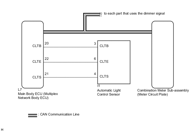
WIRING DIAGRAM
CAUTION / NOTICE / HINT
Tech Tips
Before starting the following inspection, check if the lighting system outputs DTCs Click here.
PROCEDURE
-
CHECK CAN COMMUNICATION SYSTEM
-
Check if CAN communication DTCs are output Click here.
Result Result Proceed to CAN communication DTCs are not output. A CAN communication DTCs are output. B
B 
GO TO CAN COMMUNICATION SYSTEM Click here
A 
-
-
READ VALUE USING GTS (ILLUMINATION RATE INFO)
-
Connect the GTS to the DLC3.
-
Turn the power switch on (IG).
-
Turn the GTS on.
-
Enter the following menus: Body Electrical / Main Body / Data List.
-
Check the values by referring to the table below.
Main Body Tester Display Measurement Item/Range Normal Condition Diagnostic Note Illumination Rate Info Illumination rate information/0 ms. to 99.99 ms. Value output according to ambient light level - Result Result Proceed to The output value changes according to the ambient light level. A The output value does not change according to the ambient light level. B
B
CHECK CUSTOMIZE PARAMETER SETTING (SENSITIVITY) Click here
A
-
-
REPLACE METER CIRCUIT PLATE
-
Replace the meter circuit plate with a new or a known good one Click here.
OK The operation of the combination meter sub-assembly returns to normal.
OK
END
NG
REPLACE MAIN BODY ECU (MULTIPLEX NETWORK BODY ECU) Click here
-