SFI SYSTEM, Diagnostic DTC:P0516, P0517
| DTC Code | DTC Name |
|---|---|
| P0516 | Battery Temperature Sensor Circuit Low |
| P0517 | Battery Temperature Sensor Circuit High |
DESCRIPTION
The battery temperature sensor detects battery temperature.
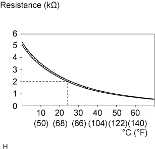
A thermistor is integrated into the battery temperature sensor, and the resistance in the battery temperature sensor changes according to the battery temperature.
The resistance of the thermistor in the battery temperature sensor decreases as the battery temperature increases. The resistance increases as the temperature decreases.
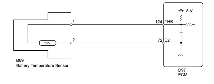
The battery temperature sensor is connected to the ECM. The ECM supplies 5 V from the THB terminal to the battery temperature sensor through resistor R.
The battery thermometer sensor and resistor R are connected in series. This results in fluctuations in the voltage supplied from the THB terminal when the resistance changes according to the battery temperature.
The ECM determines the battery temperature according to fluctuations in voltage. When the battery temperature is high, the ECM determines to reduce the amount of current supplied from the generator in order to protect the battery.
| DTC No. | DTC Detection Condition | Trouble Area |
|---|---|---|
| P0516 | Battery temperature sensor output value is 0.2 V or less for 0.5 seconds or more (1 trip detection logic) |
|
| P0517 | Battery temperature sensor output value is 4.8 V or more for 0.5 seconds or more (1 trip detection logic) |
|
WIRING DIAGRAM
INSPECTION PROCEDURE
Tech Tips
Read freeze frame data using the intelligent tester. Freeze frame data records the engine condition when malfunctions are detected. When troubleshooting, freeze frame data can help determine if the vehicle was moving or stationary, if the engine was warmed up or not, if the air fuel ratio was lean or rich, and other data from the time the malfunction occurred.
PROCEDURE
-
INSPECT BATTERY TEMPERATURE SENSOR
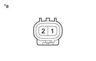
Text in Illustration *a Component without harness connected
(Battery Temperature Sensor)
-
Disconnect the battery temperature sensor connector.
-
Measure the resistance according to the value(s) in the table below.
Standard Resistance Tester Connection Condition Specified Condition 1 - 2 24 to 26°C (75 to 79°F) 1.91 to 2.05 kΩ -
Reconnect the battery temperature sensor connector.
NG 
REPLACE BATTERY TEMPERATURE SENSOR
OK 
-
-
CHECK HARNESS AND CONNECTOR (BATTERY TEMPERATURE SENSOR - ECM)
-
Disconnect the battery temperature sensor connector.
-
Disconnect the ECM connector.
-
Measure the resistance according to the value(s) in the table below.
Standard Resistance Tester Connection Condition Specified Condition B69-1 - D97-124 (THB) Always Below 1 Ω B69-2 - D97-72 (E2) Always Below 1 Ω B69-1 or D97-124 (THB) - Body ground Always 10 kΩ or higher
NG
REPAIR OR REPLACE HARNESS OR CONNECTOR
OK 
REPLACE ECM Click here
-