AUDIO AND VISUAL SYSTEM Speaker Circuit
DESCRIPTION
If there is a short in a speaker circuit, the stereo component amplifier assembly detects it and stops output to the speakers.
As a result, sound cannot be heard from the speakers even if there is no malfunction in the stereo component amplifier assembly, DCM (telematics transceiver)* or speakers.
-
*: w/ Telematics Transceiver
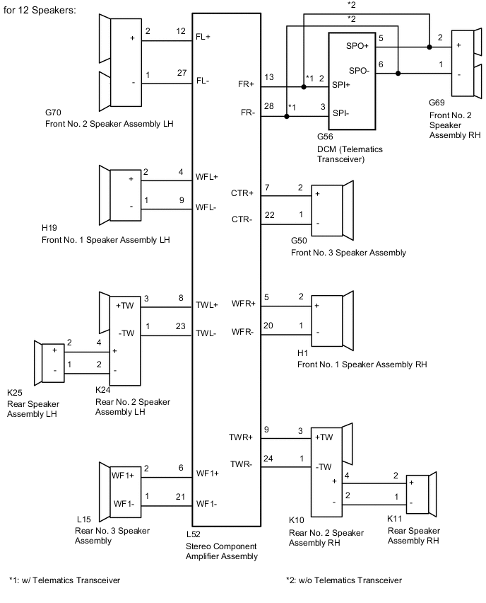
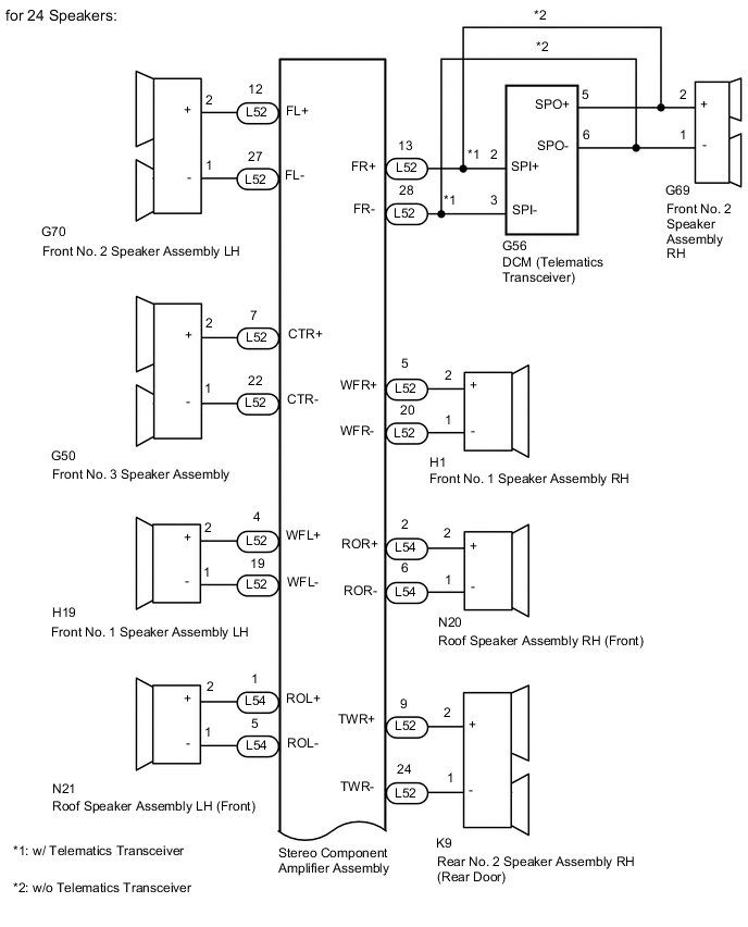
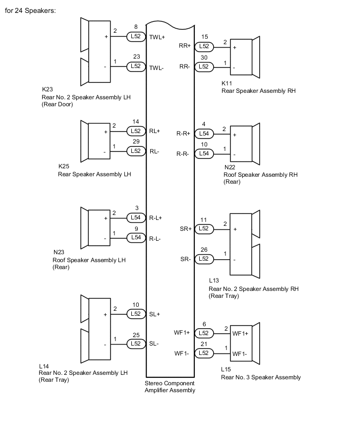
WIRING DIAGRAM
CAUTION / NOTICE / HINT
Tech Tips
Depending on the parts that are replaced during vehicle inspection or maintenance, performing initialization, registration or calibration may be needed. Refer to Precaution for Audio and Visual System.
PROCEDURE
-
CHECK VEHICLE TYPE
-
Check the vehicle type.
Result Result Proceed to for 12 Speakers A for 24 Speakers B
B 
CHECK HARNESS AND CONNECTOR (SPEAKER CIRCUIT) Click here
A 
-
-
CHECK HARNESS AND CONNECTOR (SPEAKER CIRCUIT)
-
*1: for LH Side
*2: for RH Side
*3: w/ Telematics Transceiver
-
Disconnect the L52 stereo component amplifier assembly connector.
-
Disconnect the H19*1 and/or H1*2 front No. 1 speaker assembly connector.
-
Disconnect the G70*1 and/or G69*2 front No. 2 speaker assembly connector.
-
Disconnect the G50 front No. 3 speaker assembly connector.
-
Disconnect the K25*1 and/or K11*2 rear speaker assembly connector.
-
Disconnect the K24*1 and/or K10*2 rear No. 2 speaker assembly connector.
-
Disconnect the L15 rear No. 3 speaker assembly connector.
-
Disconnect the G56 DCM (telematics transceiver) connector.*3
-
Measure the resistance according to the value(s) in the table below.
Standard Resistance for LH Side: Tester Connection Condition Specified Condition L52-4 (WFL+) - H19-2 (+) Always Below 1 Ω L52-19 (WFL-) - H19-1 (-) Always Below 1 Ω L52-12 (FL+) - G70-2 (+) Always Below 1 Ω L52-27 (FL-) - G70-1 (-) Always Below 1 Ω L52-8 (TWL+) - K24-3 (+TW) Always Below 1 Ω L52-23 (TWL-) - K24-1 (-TW) Always Below 1 Ω K24-4 (+) - K25-2 (+) Always Below 1 Ω K24-2 (-) - K25-1 (-) Always Below 1 Ω L52-4 (WFL+) - Body ground Always 10 kΩ or higher L52-19 (WFL-) - Body ground Always 10 kΩ or higher L52-12 (FL+) - Body ground Always 10 kΩ or higher L52-27 (FL-) - Body ground Always 10 kΩ or higher L52-8 (TWL+) - Body ground Always 10 kΩ or higher L52-23 (TWL-) - Body ground Always 10 kΩ or higher K24-4 (+) - Body ground Always 10 kΩ or higher K24-2 (-) - Body ground Always 10 kΩ or higher for RH Side (w/ Telematics Transceiver): Tester Connection Condition Specified Condition L52-5 (WFR+) - H1-2 (+) Always Below 1 Ω L52-20 (WFR-) - H1-1 (-) Always Below 1 Ω L52-13 (FR+) - G56-2 (SPI+) Always Below 1 Ω L52-28 (FR-) - G56-3 (SPI-) Always Below 1 Ω G56-5 (SPO+) - G69-2 (+) Always Below 1 Ω G56-6 (SPO-) - G69-1 (-) Always Below 1 Ω L52-9 (TWR+) - K10-3 (+TW) Always Below 1 Ω L52-24 (TWR-) - K10-1 (-TW) Always Below 1 Ω K10-4 (+) - K11-2 (+) Always Below 1 Ω K10-2 (-) - K11-1 (-) Always Below 1 Ω L52-5 (WFR+) - Body ground Always 10 kΩ or higher L52-20 (WFR-) - Body ground Always 10 kΩ or higher L52-13 (FR+) - Body ground Always 10 kΩ or higher L52-28 (FR-) - Body ground Always 10 kΩ or higher G56-5 (SPO+) - Body ground Always 10 kΩ or higher G56-6 (SPO-) - Body ground Always 10 kΩ or higher L52-9 (TWR+) - Body ground Always 10 kΩ or higher L52-24 (TWR-) - Body ground Always 10 kΩ or higher K10-4 (+) - Body ground Always 10 kΩ or higher K10-2 (-) - Body ground Always 10 kΩ or higher for RH Side (w/o Telematics Transceiver): Tester Connection Condition Specified Condition L52-5 (WFR+) - H1-2 (+) Always Below 1 Ω L52-20 (WFR-) - H1-1 (-) Always Below 1 Ω L52-13 (FR+) - G69-2 (+) Always Below 1 Ω L52-28 (FR-) - G69-1 (-) Always Below 1 Ω L52-9 (TWR+) - K10-3 (+TW) Always Below 1 Ω L52-24 (TWR-) - K10-1 (-TW) Always Below 1 Ω K10-4 (+) - K11-2 (+) Always Below 1 Ω K10-2 (-) - K11-1 (-) Always Below 1 Ω L52-5 (WFR+) - Body ground Always 10 kΩ or higher L52-20 (WFR-) - Body ground Always 10 kΩ or higher L52-13 (FR+) - Body ground Always 10 kΩ or higher L52-28 (FR-) - Body ground Always 10 kΩ or higher L52-9 (TWR+) - Body ground Always 10 kΩ or higher L52-24 (TWR-) - Body ground Always 10 kΩ or higher K10-4 (+) - Body ground Always 10 kΩ or higher K10-2 (-) - Body ground Always 10 kΩ or higher for Center Side: Tester Connection Condition Specified Condition L52-7 (CTR+) - G50-2 (+) Always Below 1 Ω L52-22 (CTR-) - G50-1 (-) Always Below 1 Ω L52-6 (WF1+) - L15-2 (+) Always Below 1 Ω L52-21 (WF1-) - L15-1 (-) Always Below 1 Ω L52-7 (CTR+) - Body ground Always 10 kΩ or higher L52-22 (CTR-) - Body ground Always 10 kΩ or higher L52-6 (WF1+) - Body ground Always 10 kΩ or higher L52-21 (WF1-) - Body ground Always 10 kΩ or higher Result Proceed to OK NG
NG 
REPAIR OR REPLACE HARNESS OR CONNECTOR
OK
-
-
INSPECT FRONT NO. 3 SPEAKER ASSEMBLY
-
Remove the front No. 3 speaker assembly.
-
Inspect the front No. 3 speaker assembly.
Result Proceed to OK NG
NG
REPLACE FRONT NO. 3 SPEAKER ASSEMBLY Click here
OK
-
-
INSPECT FRONT NO. 1 SPEAKER ASSEMBLY
-
Remove the front No. 1 speaker assembly.
-
Inspect the front No. 1 speaker assembly.
Result Proceed to OK NG
NG
REPLACE FRONT NO. 1 SPEAKER ASSEMBLY Click here
OK
-
-
INSPECT REAR SPEAKER ASSEMBLY
-
Remove the rear door speaker assembly.
-
Inspect the rear door speaker assembly.
Result Proceed to OK NG
NG
REPLACE REAR SPEAKER ASSEMBLY Click here
OK
-
-
INSPECT REAR NO. 3 SPEAKER ASSEMBLY
-
Remove the rear No. 3 speaker assembly.
-
Inspect the rear No. 3 speaker assembly.
Result Proceed to OK NG
NG
REPLACE REAR NO. 3 SPEAKER ASSEMBLY Click here
OK
-
-
CHECK VEHICLE TYPE
-
Check the vehicle type.
Result Result Proceed to w/ Telematics Transceiver A w/o Telematics Transceiver B
B
GO TO STEP 9 Click here
A
-
-
INSPECT DCM (TELEMATICS TRANSCEIVER) (SPO+, SPO-, SPI+, SPI-)
-
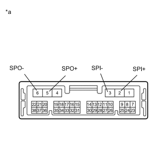
*a Component without harness connected
(DCM [Telematics Transceiver])
Remove the DCM (telematics transceiver).
-
Measure the resistance according to the value(s) in the table below.
Standard Resistance Tester Connection Condition Specified Condition 5 (SPO+) - 2 (SPI+) Always Below 1 Ω 6 (SPO-) - 3 (SPI-) Always Below 1 Ω 5 (SPO+) - Body ground Always 10 kΩ or higher 6 (SPO-) - Body ground Always 10 kΩ or higher 2 (SPI+) - 3 (SPI-) Always 10 kΩ or higher 5 (SPO+) - 6 (SPO-) Always 10 kΩ or higher Result Proceed to OK NG
NG
REPLACE DCM (TELEMATICS TRANSCEIVER) Click here
OK
-
-
CHECK FRONT NO. 2 SPEAKER ASSEMBLY
-
Replace the front No. 2 speaker assembly with a new or known good one.
-
Check the malfunction disappears.
OK Malfunction disappears. Tech Tips
-
Connect all the connectors to the front No. 2 speaker assemblies that were disconnected.
-
When there is a possibility that either the right or left front speaker is defective, inspect by interchanging the right one with the left one.
-
Perform the above inspection on both the LH and RH sides.
Result Proceed to OK NG -
OK
END (FRONT NO. 2 SPEAKER ASSEMBLY IS DEFECTIVE)
NG
-
-
CHECK REAR NO. 2 SPEAKER ASSEMBLY
-
Replace the rear No. 2 speaker assembly with a new or known good one.
-
Check the malfunction disappears.
OK Malfunction disappears. Tech Tips
-
Connect all the connectors to the rear No. 2 speaker assemblies that were disconnected.
-
When there is a possibility that either the right or left front speaker is defective, inspect by interchanging the right one with the left one.
-
Perform the above inspection on both the LH and RH sides.
Result Proceed to OK NG -
OK
END (REAR NO. 2 SPEAKER ASSEMBLY IS DEFECTIVE)
NG
REPLACE STEREO COMPONENT AMPLIFIER ASSEMBLY Click here
-
-
CHECK HARNESS AND CONNECTOR (SPEAKER CIRCUIT)
-
*1: for LH Side
*2: for RH Side
*3: w/ Telematics Transceiver
-
Disconnect the L52 and L54 stereo component amplifier assembly connector.
-
Disconnect the H19*1 and/or H1*2 front No. 1 speaker assembly connector.
-
Disconnect the G70*1 and/or G69*2 front No. 2 speaker assembly connector.
-
Disconnect the G50 front No. 3 speaker assembly connector.
-
Disconnect the N21*1 and/or N20*2 roof speaker assembly (front) connector.
-
Disconnect the K25*1 and/or K11*2 rear speaker assembly connector.
-
Disconnect the K23*1 and/or K9*2 rear No. 2 speaker assembly (rear door) connector.
-
Disconnect the N23*1 and/or N22*2 roof speaker assembly (rear) connector.
-
Disconnect the L14*1 and/or L13*2 rear No. 2 speaker assembly (rear tray) connector.
-
Disconnect the L15 rear No. 3 speaker assembly connector.
-
Disconnect the G56 DCM (telematics transceiver) connector.*3
-
Measure the resistance according to the value(s) in the table below.
Standard Resistance for LH Side: Tester Connection Condition Specified Condition L52-4 (WFL+) - H19-2 (+) Always Below 1 Ω L52-19 (WFL-) - H19-1 (-) Always Below 1 Ω L52-12 (FL+) - G70-2 (+) Always Below 1 Ω L52-27 (FL-) - G70-1 (-) Always Below 1 Ω L52-8 (TWL+) - K23-2 (+) Always Below 1 Ω L52-23 (TWL-) - K23-1 (-) Always Below 1 Ω L54-1 (ROL+) - N21-2 (+) Always Below 1 Ω L54-5 (ROL-) - N21-1 (-) Always Below 1 Ω L52-14 (RL+) - K25-2 (+) Always Below 1 Ω L52-29 (RL-) - K25-1 (-) Always Below 1 Ω L54-3 (R-L+) - N23-2 (+) Always Below 1 Ω L54-9 (R-L-) - N23-1 (-) Always Below 1 Ω L52-10 (SL+) - L14-2 (+) Always Below 1 Ω L52-25 (SL-) - L14-1 (-) Always Below 1 Ω L52-4 (WFL+) - Body ground Always 10 kΩ or higher L52-19 (WFL-) - Body ground Always 10 kΩ or higher L52-12 (FL+) - Body ground Always 10 kΩ or higher L52-27 (FL-) - Body ground Always 10 kΩ or higher L52-8 (TWL+) - Body ground Always 10 kΩ or higher L52-23 (TWL-) - Body ground Always 10 kΩ or higher L54-1 (ROL+) - Body ground Always 10 kΩ or higher L54-5 (ROL-) - Body ground Always 10 kΩ or higher L52-14 (RL+) - Body ground Always 10 kΩ or higher L52-29 (RL-) - Body ground Always 10 kΩ or higher L54-3 (R-L+) - Body ground Always 10 kΩ or higher L54-9 (R-L-) - Body ground Always 10 kΩ or higher L52-10 (SL+) - Body ground Always 10 kΩ or higher L52-25 (SL-) - Body ground Always 10 kΩ or higher for RH Side (w/ Telematics Transceiver): Tester Conne ction Condition Specified Condition L52-5 (WFR+) - H1-2 (+) Always Below 1 Ω L52-20 (WFR-) - H1-1 (-) Always Below 1 Ω L52-13 (FR+) - G56-2 (SPI+) Always Below 1 Ω L52-28 (FR-) - G56-3 (SPI-) Always Below 1 Ω G56-5 (SPO+) - G69-2 (+) Always Below 1 Ω G56-6 (SPO-) - G69-1 (-) Always Below 1 Ω L52-9 (TWR+) - K9-2 (+) Always Below 1 Ω L52-24 (TWR-) - K9-1 (-) Always Below 1 Ω L54-2 (ROR+) - N20-2 (+) Always Below 1 Ω L54-6 (ROR-) - N20-1 (-) Always Below 1 Ω L52-15 (RR+) - K11-2 (+) Always Below 1 Ω L52-30 (RR-) - K11-1 (-) Always Below 1 Ω L54-4 (R-R+) - N22-2 (+) Always Below 1 Ω L54-10 (R-R-) - N22-1 (-) Always Below 1 Ω L52-11 (SR+) - L13-2 (+) Always Below 1 Ω L52-26 (SR-) - L13-1 (-) Always Below 1 Ω L52-5 (WFR+) - Body ground Always 10 kΩ or higher L52-20 (WFR-) - Body ground Always 10 kΩ or higher L52-13 (FR+) - Body ground Always 10 kΩ or higher L52-28 (FR-) - Body ground Always 10 kΩ or higher G56-5 (SPO+) - Body ground Always 10 kΩ or higher G56-6 (SPO-) - Body ground Always 10 kΩ or higher L52-9 (TWR+) - Body ground Always 10 kΩ or higher L52-24 (TWR-) - Body ground Always 10 kΩ or higher L54-2 (ROR+) - Body ground Always 10 kΩ or higher L54-6 (ROR-) - Body ground Always 10 kΩ or higher L52-15 (RR+) - Body ground Always 10 kΩ or higher L52-30 (RR-) - Body ground Always 10 kΩ or higher L54-4 (R-R+) - Body ground Always 10 kΩ or higher L54-10 (R-R-) - Body ground Always 10 kΩ or higher L52-11 (SR+) - Body ground Always 10 kΩ or higher L52-26 (SR-) - Body ground Always 10 kΩ or higher for RH Side (w/o Telematics Transceiver): Tester Conne ction Condition Specified Condition L52-5 (WFR+) - H1-2 (+) Always Below 1 Ω L52-20 (WFR-) - H1-1 (-) Always Below 1 Ω L52-13 (FR+) - G69-2 (+) Always Below 1 Ω L52-28 (FR-) - G69-1 (-) Always Below 1 Ω L52-9 (TWR+) - K9-2 (+) Always Below 1 Ω L52-24 (TWR-) - K9-1 (-) Always Below 1 Ω L54-2 (ROR+) - N20-2 (+) Always Below 1 Ω L54-6 (ROR-) - N20-1 (-) Always Below 1 Ω L52-15 (RR+) - K11-2 (+) Always Below 1 Ω L52-30 (RR-) - K11-1 (-) Always Below 1 Ω L54-4 (R-R+) - N22-2 (+) Always Below 1 Ω L54-10 (R-R-) - N22-1 (-) Always Below 1 Ω L52-11 (SR+) - L13-2 (+) Always Below 1 Ω L52-26 (SR-) - L13-1 (-) Always Below 1 Ω L52-5 (WFR+) - Body ground Always 10 kΩ or higher L52-20 (WFR-) - Body ground Always 10 kΩ or higher L52-13 (FR+) - Body ground Always 10 kΩ or higher L52-28 (FR-) - Body ground Always 10 kΩ or higher L52-9 (TWR+) - Body ground Always 10 kΩ or higher L52-24 (TWR-) - Body ground Always 10 kΩ or higher L54-2 (ROR+) - Body ground Always 10 kΩ or higher L54-6 (ROR-) - Body ground Always 10 kΩ or higher L52-15 (RR+) - Body ground Always 10 kΩ or higher L52-30 (RR-) - Body ground Always 10 kΩ or higher L54-4 (R-R+) - Body ground Always 10 kΩ or higher L54-10 (R-R-) - Body ground Always 10 kΩ or higher L52-11 (SR+) - Body ground Always 10 kΩ or higher L52-26 (SR-) - Body ground Always 10 kΩ or higher for Center Side: Tester Connection Condition Specified Condition L52-7 (CTR+) - G50-2 (+) Always Below 1 Ω L52-22 (CTR-) - G50-1 (-) Always Below 1 Ω L52-6 (WF1+) - L15-2 (+) Always Below 1 Ω L52-21 (WF1-) - L15-1 (-) Always Below 1 Ω L52-7 (CTR+) - Body ground Always 10 kΩ or higher L52-22 (CTR-) - Body ground Always 10 kΩ or higher L52-6 (WF1+) - Body ground Always 10 kΩ or higher L52-21 (WF1-) - Body ground Always 10 kΩ or higher Result Proceed to OK NG
NG
REPAIR OR REPLACE HARNESS OR CONNECTOR
OK
-
-
INSPECT FRONT NO. 1 SPEAKER ASSEMBLY
-
Remove the front No. 1 speaker assembly.
-
Inspect the front No. 1 speaker assembly.
Result Proceed to OK NG
NG
REPLACE FRONT NO. 1 SPEAKER ASSEMBLY Click here
OK
-
-
INSPECT ROOF SPEAKER ASSEMBLY (FRONT)
-
Remove the roof speaker assembly (front).
-
Inspect the roof speaker assembly (front).
Result Proceed to OK NG
NG
REPLACE ROOF SPEAKER ASSEMBLY (FRONT) Click here
OK
-
-
INSPECT ROOF SPEAKER ASSEMBLY (REAR)
-
Remove the roof speaker assembly (rear).
-
Inspect the roof speaker assembly (rear).
Result Proceed to OK NG
NG
REPLACE ROOF SPEAKER ASSEMBLY (REAR) Click here
OK
-
-
INSPECT REAR SPEAKER ASSEMBLY
-
Remove the rear door speaker assembly.
-
Inspect the rear door speaker assembly.
Result Proceed to OK NG
NG
REPLACE REAR SPEAKER ASSEMBLY Click here
OK
-
-
INSPECT REAR NO. 3 SPEAKER ASSEMBLY
-
Remove the rear No. 3 speaker assembly.
-
Inspect the rear No. 3 speaker assembly.
Result Proceed to OK NG
NG
REPLACE REAR NO. 3 SPEAKER ASSEMBLY Click here
OK
-
-
CHECK VEHICLE TYPE
-
Check the vehicle type.
Result Result Proceed to w/ Telematics Transceiver A w/o Telematics Transceiver B
B
GO TO STEP 19 Click here
A
-
-
INSPECT DCM (TELEMATICS TRANSCEIVER) (SPO+, SPO-, SPI+, SPI-)
-
*a Component without harness connected
(DCM [Telematics Transceiver])
Remove the DCM (telematics transceiver).
-
Measure the resistance according to the value(s) in the table below.
Standard Resistance Tester Connection Condition Specified Condition 5 (SPO+) - 2 (SPI+) Always Below 1 Ω 6 (SPO-) - 3 (SPI-) Always Below 1 Ω 5 (SPO+) - Body ground Always 10 kΩ or higher 6 (SPO-) - Body ground Always 10 kΩ or higher 2 (SPI+) - 3 (SPI-) Always 10 kΩ or higher 5 (SPO+) - 6 (SPO-) Always 10 kΩ or higher Result Proceed to OK NG
NG
REPLACE DCM (TELEMATICS TRANSCEIVER) Click here
OK
-
-
CHECK FRONT NO. 2 SPEAKER ASSEMBLY
-
Replace the front No. 2 speaker assembly with a new or known good one.
-
Check the malfunction disappears.
OK Malfunction disappears. Tech Tips
-
Connect all the connectors to the front No. 2 speaker assemblies that were disconnected.
-
When there is a possibility that either the right or left front speaker is defective, inspect by interchanging the right one with the left one.
-
Perform the above inspection on both the LH and RH sides.
Result Proceed to OK NG -
OK
END (FRONT NO. 2 SPEAKER ASSEMBLY IS DEFECTIVE)
NG
-
-
CHECK FRONT NO. 3 SPEAKER ASSEMBLY
-
Replace the front No. 3 speaker assembly with a new or known good one.
-
Check the malfunction disappears.
OK Malfunction disappears. Tech Tips
-
Connect all the connectors to the front No. 3 speaker assemblies that were disconnected.
-
When there is a possibility that either the right or left front speaker is defective, inspect by interchanging the right one with the left one.
Result Proceed to OK NG -
OK
END (FRONT NO. 3 SPEAKER ASSEMBLY IS DEFECTIVE)
NG
-
-
CHECK REAR NO. 2 SPEAKER ASSEMBLY [REAR DOOR]
-
Replace the rear No. 2 speaker assembly (rear door) with a new or known good one.
-
Check the malfunction disappears.
OK Malfunction disappears. Tech Tips
-
Connect all the connectors to the front No. 2 speaker assemblies (rear door) that were disconnected.
-
When there is a possibility that either the right or left front speaker is defective, inspect by interchanging the right one with the left one.
-
Perform the above inspection on both the LH and RH sides.
Result Proceed to OK NG -
OK
END (REAR NO. 2 SPEAKER ASSEMBLY [REAR DOOR] IS DEFECTIVE)
NG
-
-
CHECK REAR NO. 2 SPEAKER ASSEMBLY [REAR TRAY]
-
Replace the rear No. 2 speaker assembly (rear tray) with a new or known good one.
-
Check the malfunction disappears.
OK Malfunction disappears. Tech Tips
-
Connect all the connectors to the front No. 2 speaker assemblies (rear tray) that were disconnected.
-
When there is a possibility that either the right or left front speaker is defective, inspect by interchanging the right one with the left one.
-
Perform the above inspection on both the LH and RH sides.
Result Proceed to OK NG -
OK
END (REAR NO. 2 SPEAKER ASSEMBLY [REAR TRAY] IS DEFECTIVE)
NG
REPLACE STEREO COMPONENT AMPLIFIER ASSEMBLY Click here
-