LIGHTING SYSTEM(w/ Automatic Headlight Beam Level Control System) Taillight Relay Circuit
DESCRIPTION
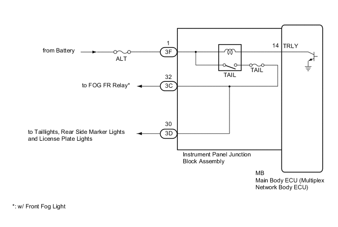
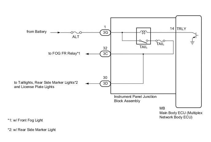
The main body ECU (multiplex network body ECU) controls the operation of the TAIL relay.
WIRING DIAGRAM
-
for LHD
-
for RHD
CAUTION / NOTICE / HINT
Note
-
Inspect the fuses for circuits related to this system before performing the following procedure.
-
The vehicle battery supplies power to the main body ECU (multiplex network body ECU) via the door control battery. Therefore, before performing this troubleshooting procedure, make sure to perform an on-vehicle inspection to confirm that the main body ECU (multiplex network body ECU) power source circuit is normal.*1
-
Before replacing the main body ECU (multiplex network body ECU), refer to Service Bulletin.*2
-
*1: w/ Door Control Battery
-
*2: w/ Smart Entry and Start System
PROCEDURE
-
PERFORM ACTIVE TEST USING GTS
-
Connect the GTS to the DLC3.
-
Turn the ignition switch to ON.
-
Turn the GTS on.
-
Enter the following menus: Body Electrical / Main Body / Active Test.
-
Perform the Active Test according to the display on the GTS.
Body Electrical > Main Body > Active TestTester Display Measurement Item Control Range Diagnostic Note Taillight Relay Taillight relay OFF or ON -
Body Electrical > Main Body > Active TestTester Display Taillight Relay OK Taillights illuminate. Result Proceed to OK NG
OK 
PROCEED TO NEXT SUSPECTED AREA SHOWN IN PROBLEM SYMPTOMS TABLE Click here
NG 
-
-
CHECK HARNESS AND CONNECTOR (POWER SOURCE - INSTRUMENT PANEL JUNCTION BLOCK ASSEMBLY)
-
Disconnect the 3F*1 or 3G*2 instrument panel junction block assembly connector.
-
*1: for LHD
-
*2: for RHD
-
-
Measure the voltage according to the value(s) in the table below.
Standard Voltage for LHD Tester Connection Condition Specified Condition 3F-1 - Body ground Always 11 to 14 V for RHD Tester Connection Condition Specified Condition 3G-1 - Body ground Always 11 to 14 V Result Proceed to OK NG
NG
REPAIR OR REPLACE HARNESS OR CONNECTOR
OK
-
-
INSPECT INSTRUMENT PANEL JUNCTION BLOCK ASSEMBLY
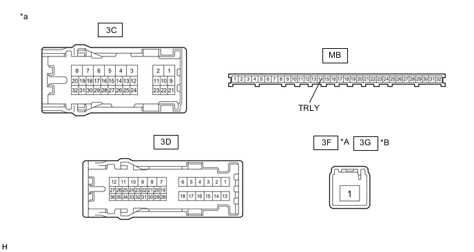
*A for LHD *B for RHD *a Component without harness connected
(Instrument Panel Junction Block Assembly)
- -
-
Remove the instrument panel junction block assembly.
-
Remove the main body ECU (multiplex network body ECU) from the instrument panel junction block assembly.
-
Connect a positive (+) lead from the battery to terminal 3F-1*1 or 3G-1*2.
-
*1: for LHD
-
*2: for RHD
-
-
Connect a negative (-) lead from the battery to terminal MB-14 (TRLY).
-
Measure the voltage according to the value(s) in the table below.
Standard Voltage Tester Connection Condition Specified Condition 3C-32 - Battery negative (-) terminal* Always 11 to 14 V 3D-30 - Battery negative (-) terminal Always 11 to 14 V
-
*: w/ Front Fog Light
Result Proceed to OK NG -
OK
REPLACE MAIN BODY ECU (MULTIPLEX NETWORK BODY ECU) Click here
NG
REPLACE INSTRUMENT PANEL JUNCTION BLOCK ASSEMBLY Click here
-