AUDIO AND VISUAL SYSTEM(for 8 Speakers) Speaker Circuit
DESCRIPTION
If there is a short in a speaker circuit, the stereo component amplifier assembly*1 or radio receiver assembly*2 detects it and stops output to the speakers.
As a result, sound cannot be heard from the speakers even if there is no malfunction in the stereo component amplifier assembly*1 or radio receiver assembly*2 or speakers.
-
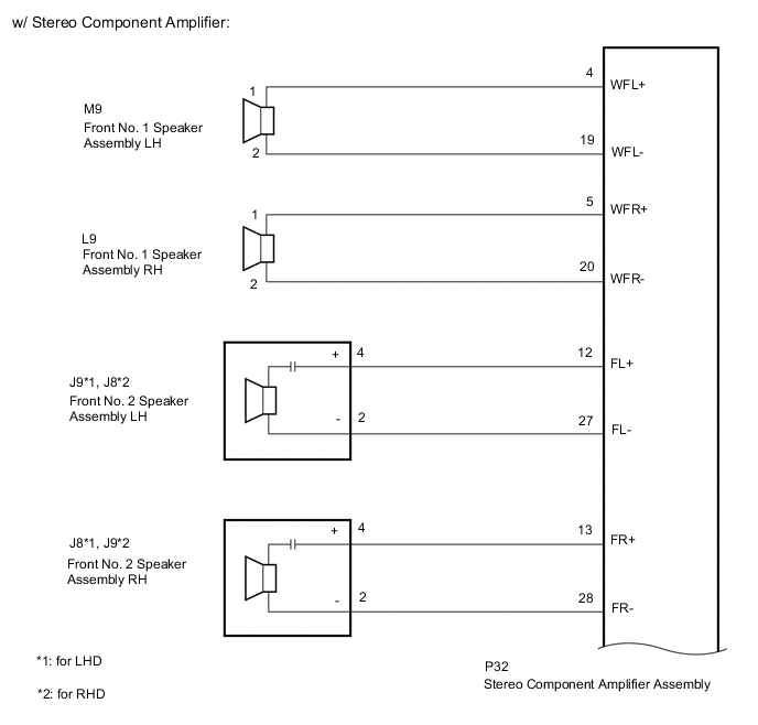
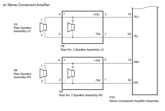
*1: w/ Stereo Component Amplifier
-
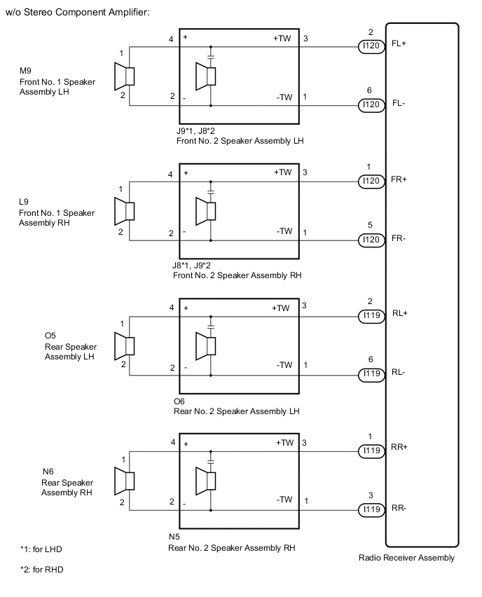
*2: w/o Stereo Component Amplifier
WIRING DIAGRAM
PROCEDURE
-
CHECK HARNESS AND CONNECTOR
-
*1: for LH Side
*2: for RH Side
*3: for LHD
*4: for RHD
*5: w/ Stereo Component Amplifier
*6: w/o Stereo Component Amplifier
-
Disconnect the P32 stereo component amplifier assembly connector*5.
-
Disconnect the I119 and I120 radio receiver assembly connectors*6.
-
Disconnect the M9*1 and/or L9*2 front No. 1 speaker assembly connector.
-
for LHD:
Disconnect the J9*1 and/or J8*2 front No. 2 speaker assembly connector.
-
for RHD:
Disconnect the J8*1 and/or J9*2 front No. 2 speaker assembly connector.
-
Disconnect the O5*1 and/or N6*2 rear speaker assembly connector.
-
Disconnect the O6*1 and/or N5*2 rear No. 2 speaker assembly connector.
-
Measure the resistance according to the value(s) in the table below.
Standard Resistance for LH Side (w/ Stereo Component Amplifier): Tester Connection Condition Specified Condition P32-4 (WFL+) - M9-1 Always Below 1 Ω P32-19 (WFL-) - M9-2 Always Below 1 Ω P32-12 (FL+) - J9-4 (+)*3 Always Below 1 Ω P32-12 (FL+) - J8-4 (+)*4 Always Below 1 Ω P32-27 (FL-) - J9-2 (-)*3 Always Below 1 Ω P32-27 (FL-) - J8-2 (-)*4 Always Below 1 Ω P32-14 (RL+) - O6-3 (+TW) Always Below 1 Ω P32-29 (RL-) - O6-1 (-TW) Always Below 1 Ω O6-4 (+) - O5-1 Always Below 1 Ω O6-2 (-) - O5-2 Always Below 1 Ω P32-4 (WFL+) or M9-1 - Body ground Always 10 kΩ or higher P32-19 (WFL-) or M9-2 - Body ground Always 10 kΩ or higher P32-12 (FL+) or J9-4 (+) - Body ground*3 Always 10 kΩ or higher P32-12 (FL+) or J8-4 (+) - Body ground*4 Always 10 kΩ or higher P32-27 (FL-) or J9-2 (-) - Body ground*3 Always 10 kΩ or higher P32-27 (FL-) or J8-2 (-) - Body ground*4 Always 10 kΩ or higher P32-14 (RL+) or O6-3 (+TW) - Body ground Always 10 kΩ or higher P32-29 (RL-) or O6-1 (-TW) - Body ground Always 10 kΩ or higher O6-4 (+) or O5-1 - Body ground Always 10 kΩ or higher O6-2 (-) or O5-2 - Body ground Always 10 kΩ or higher for LH Side (w/o Stereo Component Amplifier): Tester Connection Condition Specified Condition I120-2 (FL+) - J9-3 (+TW)*3 Always Below 1 Ω I120-2 (FL+) - J8-3 (+TW)*4 Always Below 1 Ω I120-6 (FL-) - J9-1 (-TW)*3 Always Below 1 Ω I120-6 (FL-) - J8-1 (-TW)*4 Always Below 1 Ω J9-4 (+) - M9-1*3 Always Below 1 Ω J8-4 (+) - M9-1*4 Always Below 1 Ω J9-2 (-) - M9-2*3 Always Below 1 Ω J8-2 (-) - M9-2*4 Always Below 1 Ω I119-2 (RL+) - O6-3 (+TW) Always Below 1 Ω I119-6 (RL-) - O6-1 (-TW) Always Below 1 Ω O6-4 (+) - O5-1 Always Below 1 Ω O6-2 (-) - O5-2 Always Below 1 Ω I120-2 (FL+) or J9-3 (+TW) - Body ground*3 Always 10 kΩ or higher I120-2 (FL+) or J8-3 (+TW) - Body ground*4 Always 10 kΩ or higher I120-6 (FL-) or J9-1 (-TW) - Body ground*3 Always 10 kΩ or higher I120-6 (FL-) or J8-1 (-TW) - Body ground*4 Always 10 kΩ or higher J9-4 (+) or M9-1 - Body ground*3 Always 10 kΩ or higher J8-4 (+) or M9-1 - Body ground*4 Always 10 kΩ or higher J9-2 (-) or M9-2 - Body ground*3 Always 10 kΩ or higher J8-2 (-) or M9-2 - Body ground*4 Always 10 kΩ or higher I119-2 (RL+) or O6-3 (+TW) - Body ground Always 10 kΩ or higher I119-6 (RL-) or O6-1 (-TW) - Body ground Always 10 kΩ or higher O6-4 (+) or O5-1 - Body ground Always 10 kΩ or higher O6-2 (-) or O5-2 - Body ground Always 10 kΩ or higher for RH Side (w/ Stereo Component Amplifier): Tester Connection Condition Specified Condition P32-5 (WFR+) - L9-1 Always Below 1 Ω P32-20 (WFR-) - L9-2 Always Below 1 Ω P32-13 (FR+) - J8-4 (+)*3 Always Below 1 Ω P32-13 (FR+) - J9-4 (+)*4 Always Below 1 Ω P32-28 (FR-) - J8-2 (-)*3 Always Below 1 Ω P32-28 (FR-) - J9-2 (-)*4 Always Below 1 Ω P32-15 (RR+) - N5-3 (+TW) Always Below 1 Ω P32-30 (RR-) - N5-1 (-TW) Always Below 1 Ω N5-4 (+) - N6-1 Always Below 1 Ω N5-2 (-) - N6-2 Always Below 1 Ω P32-5 (WFR+) or L9-1 - Body ground Always 10 kΩ or higher P32-20 (WFR-) or L9-2 - Body ground Always 10 kΩ or higher P32-13 (FR+) or J8-4 (+) - Body ground*3 Always 10 kΩ or higher P32-13 (FR+) or J9-4 (+) - Body ground*4 Always 10 kΩ or higher P32-28 (FR-) - J8-2 (-) - Body ground*3 Always 10 kΩ or higher P32-28 (FR-) - J9-2 (-) - Body ground*4 Always 10 kΩ or higher P32-15 (RR+) or N5-3 (+TW) - Body ground Always 10 kΩ or higher P32-30 (RR-) or N5-1 (-TW) - Body ground Always 10 kΩ or higher N5-4 (+) or N6-1 - Body ground Always 10 kΩ or higher N5-2 (-) or N6-2 - Body ground Always 10 kΩ or higher for RH Side (w/o Stereo Component Amplifier): Tester Connection Condition Specified Condition I120-1 (FR+) - J8-3 (+TW)*3 Always Below 1 Ω I120-1 (FR+) - J9-3 (+TW)*4 Always Below 1 Ω I120-5 (FR-) - J8-1 (-TW)*3 Always Below 1 Ω I120-5 (FR-) - J9-1 (-TW)*4 Always Below 1 Ω J8-4 (+) - L9-1*3 Always Below 1 Ω J9-4 (+) - L9-1*4 Always Below 1 Ω J8-2 (-) - L9-2*3 Always Below 1 Ω J9-2 (-) - L9-2*4 Always Below 1 Ω I119-1 (RR+) - N5-3 (+TW) Always Below 1 Ω I119-3 (RR-) - N5-1 (-TW) Always Below 1 Ω N5-4 (+) - N6-1 Always Below 1 Ω N5-2 (-) - N6-2 Always Below 1 Ω I120-1 (FR+) or J8-3 (+TW) - Body ground*3 Always 10 kΩ or higher I120-1 (FR+) or J9-3 (+TW) - Body ground*4 Always 10 kΩ or higher I120-5 (FR-) or J8-1 (-TW) - Body ground*3 Always 10 kΩ or higher I120-5 (FR-) or J9-1 (-TW) - Body ground*4 Always 10 kΩ or higher J8-4 (+) or L9-1 - Body ground*3 Always 10 kΩ or higher J9-4 (+) or L9-1 - Body ground*4 Always 10 kΩ or higher J8-2 (-) or L9-2 - Body ground*3 Always 10 kΩ or higher J9-2 (-) or L9-2 - Body ground*4 Always 10 kΩ or higher I119-1 (RR+) or N5-3 (+TW) - Body ground Always 10 kΩ or higher I119-3 (RR-) or N5-1 (-TW) - Body ground Always 10 kΩ or higher N5-4 (+) or N6-1 - Body ground Always 10 kΩ or higher N5-2 (-) or N6-2 - Body ground Always 10 kΩ or higher Result Proceed to OK NG
NG 
REPAIR OR REPLACE HARNESS OR CONNECTOR
OK 
-
-
INSPECT FRONT NO. 1 SPEAKER ASSEMBLY
-
Remove the front No. 1 speaker assembly.
-
Inspect the front No. 1 speaker assembly.
Result Proceed to OK NG
NG
REPLACE FRONT NO. 1 SPEAKER ASSEMBLY Click here
OK
-
-
INSPECT REAR SPEAKER ASSEMBLY
-
Remove the rear speaker assembly.
-
Inspect the rear speaker assembly.
Result Proceed to OK NG
NG
REPLACE REAR SPEAKER ASSEMBLY Click here
OK
-
-
CHECK FRONT NO. 2 SPEAKER ASSEMBLY
-
Replace the front No. 2 speaker assembly.
-
Check the malfunction disappears.
OK Malfunction disappears. Tech Tips
-
Connect all the connectors to the front No. 2 speaker assemblies that were disconnected.
-
When there is a possibility that either the right or left front speaker is defective, inspect by interchanging the right one with the left one.
-
Perform the above inspection on both the LH and RH sides.
Result Proceed to OK NG -
OK
END (FRONT NO. 2 SPEAKER ASSEMBLY IS DEFECTIVE)
NG
-
-
CHECK REAR NO. 2 SPEAKER ASSEMBLY
-
Replace the rear No. 2 speaker assembly.
-
Check the malfunction disappears.
OK Malfunction disappears. Tech Tips
-
Connect all the connectors to the rear No. 2 speaker assemblies that were disconnected.
-
When there is a possibility that either the right or left front speaker is defective, inspect by interchanging the right one with the left one.
-
Perform the above inspection on both the LH and RH sides.
Result Proceed to OK NG -
OK
END (REAR NO. 2 SPEAKER ASSEMBLY IS DEFECTIVE)
NG
PROCEED TO NEXT SUSPECTED AREA SHOWN IN PROBLEM SYMPTOMS TABLE Click here
-