NAVIGATION SYSTEM Reverse Signal Circuit
| DTC Code | DTC Name |
|---|---|
| Reverse Signal Circuit |
DESCRIPTION
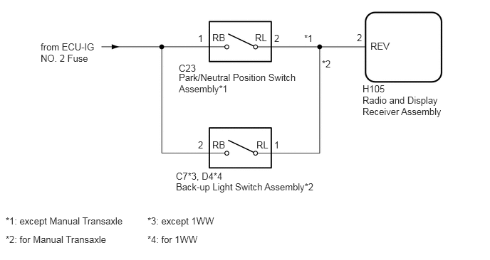
The radio and display receiver assembly receives a reverse signal from the park/neutral position switch assembly*1 or back-up light switch assembly*2.
*1: except Manual Transaxle
*2: for Manual Transaxle
WIRING DIAGRAM
CAUTION / NOTICE / HINT
Inspect the fuses for circuits related to this system before performing the following inspection procedure.
Check that the wire harness is properly installed and does not have any sharp bends, pinching or loose connections (Click here).
PROCEDURE
CHECK VEHICLE SIGNAL (OPERATION CHECK)
-
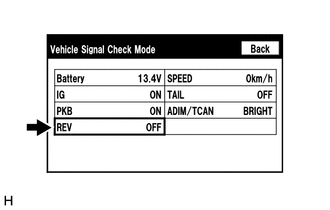
Enter the "Vehicle Signal Check Mode" screen. [Refer to check Vehicle Signal in Operation Check (Click here)].
Check that the display changes between ON and OFF according to the shift lever position.
OK
Shift Lever Position
Display
R
ON
Except R
OFF
Tip:This display is updated once per second. As a result, it is normal for the display to lag behind the actual shift lever position.
-
CHECK RADIO AND DISPLAY RECEIVER ASSEMBLY
-
Disconnect the radio and display receiver assembly connector.
Measure the voltage according to the value(s) in the table below.
Standard Voltage
Tester Connection
Switch Condition
Specified Condition
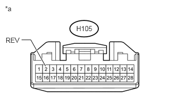
H105-2 (REV) - Body ground
Ignition switch ON, shift lever in R
7.5 to 14 V
H105-2 (REV) - Body ground
Ignition switch ON, shift lever not in R
Below 1 V
Table 1. Text in Illustration *a
Front view of wire harness connector
(to Radio and Display Receiver Assembly)
Table 2. Result Result
Proceed to
OK
A
NG (except Manual Transaxle)
B
NG (for Manual Transaxle)
C
CHECK HARNESS AND CONNECTOR (RADIO AND DISPLAY RECEIVER ASSEMBLY - BACK-UP LIGHT SWITCH ASSEMBLY)Click here
-
CHECK HARNESS AND CONNECTOR (RADIO AND DISPLAY RECEIVER ASSEMBLY - PARK/NEUTRAL POSITION SWITCH ASSEMBLY)
Disconnect the H105 radio and display receiver assembly connector.
Disconnect the C23 park/neutral position switch assembly connector.
Measure the resistance according to the value(s) in the table below.
Standard Resistance
Tester Connection
Condition
Specified Condition
H105-2 (REV) - C23-2 (RL)
Always
Below 1 Ω
H105-2 (REV) - Body ground
Always
10 kΩ or higher
REPAIR OR REPLACE HARNESS OR CONNECTOR
CHECK HARNESS AND CONNECTOR (PARK/NEUTRAL POSITION SWITCH ASSEMBLY - BATTERY)
-
Disconnect the park/neutral position switch assembly connector.
Measure the voltage according to the value(s) in the table below.
Standard Voltage
Tester Connection
Switch Condition
Specified Condition
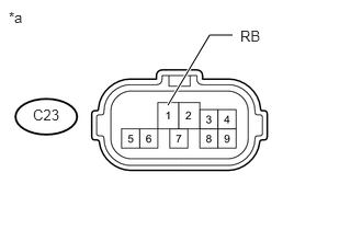
C23-1 (RB) - Body ground
Ignition switch ON
11 to 14 V
Table 3. Text in Illustration *a
Front view of wire harness connector
(to Park/neutral Position Switch Assembly)
REPAIR OR REPLACE HARNESS OR CONNECTOR
-
CHECK HARNESS AND CONNECTOR (RADIO AND DISPLAY RECEIVER ASSEMBLY - BACK-UP LIGHT SWITCH ASSEMBLY)
*1: except 1WW
*2: for 1WW
Disconnect the H105 radio and display receiver assembly connector.
Disconnect the C7*1 or D4*2 back-up light switch assembly connector.
Measure the resistance according to the value(s) in the table below.
Standard Resistance
Tester Connection
Condition
Specified Condition
H105-2 (REV) - C7-1 (RL)*1
Always
Below 1 Ω
H105-2 (REV) - D4-1 (RL)*2
Always
Below 1 Ω
H105-2 (REV) - Body ground
Always
10 kΩ or higher
REPAIR OR REPLACE HARNESS OR CONNECTOR
CHECK HARNESS AND CONNECTOR (BACK-UP LIGHT SWITCH ASSEMBLY - BATTERY)
*1: except 1WW
*2: for 1WW
-
Disconnect the back-up light switch assembly connector.
Measure the voltage according to the value(s) in the table below.
Standard Voltage
Tester Connection
Switch Condition
Specified Condition
C7-2 (RB) - Body ground*1
Ignition switch ON
11 to 14 V
D4-2 (RB) - Body ground*2
Ignition switch ON
11 to 14 V
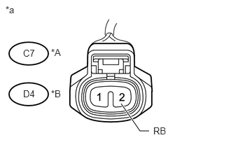
Table 4. Text in Illustration *A
except 1WW
*B
for 1WW
*a
Front view of wire harness connector
(to Back-up Light Switch Assembly)
Table 5. Result Result
Proceed to
OK (for EA65 Manual Transaxle)
A
OK (for EC61 Manual Transaxle)
B
OK (for EC62 Manual Transaxle)
C
NG
D
REPAIR OR REPLACE HARNESS OR CONNECTOR