CYLINDER BLOCK INSPECTION

PROCEDURE
-
INSPECT CYLINDER BLOCK FOR WARPAGE
-
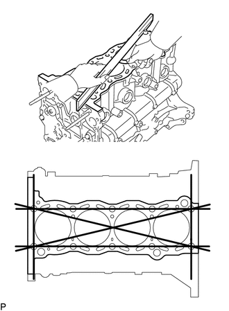
Using a precision straightedge and feeler gauge, measure the warpage of the surface that contacts the cylinder head gasket.
Maximum warpage 0.05 mm (0.00197 in.) If the warpage is more than the maximum, replace the cylinder block.
-
Visually check the cylinders for vertical scratches.
If deep scratches are present, rebore all 4 cylinders. If necessary, replace the cylinder block.
-
-
INSPECT CYLINDER BORE
-
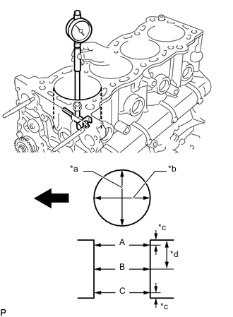
*a Thrust Direction *b Axial Direction *c 10 mm (0.394 in.) *d 70 mm (2.75 in.) 
Front Using a cylinder gauge, measure the cylinder bore diameter at position A, B and C in the thrust and axial directions.
Reference value (new parts) 94.990 to 95.003 mm (3.7398 to 3.7403 in.) Maximum diameter 95.190 mm (3.7476 in.) If the diameter is more than the maximum, rebore all 4 cylinders. If necessary, replace the cylinder block.
-
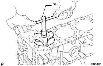
*a Ridge Reamer Inspect the cylinder ridge.
If the wear is less than 0.2 mm (0.00787 in.), using a ridge reamer, grind the top of the cylinder.
-
-
CLEAN CYLINDER BLOCK
-
Using a gasket scraper, remove all the gasket material from the top surface of the cylinder block.
-
Using a soft brush and solvent, thoroughly clean the cylinder block.
-
-
INSPECT PISTON DIAMETER
-
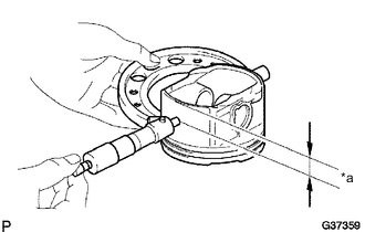
*a Distance Using a micrometer, measure the piston diameter at right angles to the piston center line where the distance from the piston end is as specified.
Distance 13.8 mm (0.543 in.) Reference value (new parts) 94.971 to 94.981 mm (3.7390 to 3.7394 in.)
-
-
INSPECT PISTON OIL CLEARANCE
-
Measure the cylinder bore diameter in the thrust direction.
-
Subtract the piston diameter measurement from the cylinder bore diameter measurement.
Reference value (new parts) 0.009 to 0.048 mm (0.000354 to 0.00189 in.) If the oil clearance is more than the standard, replace all the pistons and rebore all the cylinders. If necessary, replace the cylinder block.
-
-
INSPECT RING GROOVE CLEARANCE
-
Using a feeler gauge, measure the clearance between a new piston ring and the wall of the ring groove.
Standard Ring Groove Clearance Item Specified Condition No. 1 Compression Ring 0.020 to 0.070 mm (0.000787 to 0.00276 in.) No. 2 Compression Ring 0.020 to 0.060 mm (0.000787 to 0.00236 in.) Oil Ring 0.060 to 0.120 mm (0.00236 to 0.00472 in.) If the groove clearance is not as specified, replace the piston with pin.
-
-
INSPECT PISTON RING END GAP
-
Insert the piston ring into the cylinder bore.
-
Using a piston, push the piston ring a little beyond the bottom of the ring travel, 110 mm (4.33 in.) from the top of the cylinder block.
-
Using a feeler gauge, measure the end gap.
Standard End Gap Item Specified Condition No. 1 Compression Ring 0.30 to 0.35 mm (0.0118 to 0.0138 in.) No. 2 Compression Ring 0.59 to 0.71 mm (0.0232 to 0.0280 in.) Oil Ring 0.10 to 0.35 mm (0.00394 to 0.0138 in.) Maximum End Gap Item Specified Condition No. 1 Compression Ring 0.90 mm (0.0354 in.) No. 2 Compression Ring 1.36 mm (0.0535 in.) Oil Ring 0.75 mm (0.0295 in.) If the end gap is more than the maximum, replace the piston ring. If the end gap is less than the standard, even with a new piston ring, rebore all 4 cylinders or replace the cylinder block.
-
-
INSPECT PISTON PIN OIL CLEARANCE
Tech Tips
There is only 1 type of supply part for piston with pin sub-assembly.
-
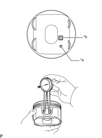
*a Front Mark *b Piston Pin Hole Inside Diameter Mark Using a caliper gauge, measure the inside diameter of the piston pin hole.
Standard Piston Pin Hole Inside Diameter Item Specified Condition A 22.001 to 22.004 mm (0.86618 to 0.86630 in.) B 22.005 to 22.007 mm (0.86634 to 0.86642 in.) C 22.008 to 22.010 mm (0.86645 to 0.86653 in.) If the diameter is not as specified, replace the piston with pin.
-
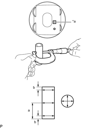
*a Piston Pin Hole Inside Diameter Mark Using a micrometer, measure the piston pin diameter.
Measurement Position Measurement Position Piston Pin Position a 28 mm (1.10 in.) b 5 mm (0.197 in.) Standard Piston Pin Diameter Item Specified Condition A 21.997 to 22.000 mm (0.86602 to 0.86614 in.) B 22.001 to 22.003 mm (0.86618 to 0.86626 in.) C 22.004 to 22.006 mm (0.86630 to 0.86638 in.) -
Subtract the piston pin diameter measurement from the piston pin hole diameter measurement.
Standard oil clearance 0.001 to 0.007 mm (0.0000394 to 0.000276 in.) Maximum oil clearance 0.010 mm (0.000394 in.) If the oil clearance is more than the maximum, replace the piston and piston pin as a set.
-
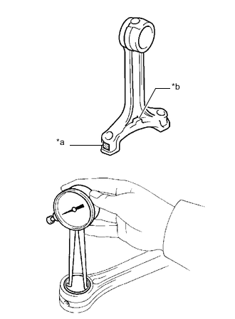
*a Connecting Rod Bush Inside Diameter Mark *b Front Mark Using a caliper gauge, measure the inside diameter of the connecting rod small end bush.
Standard Bush Inside Diameter Item Specified Condition A 22.005 to 22.008 mm (0.86634 to 0.86645 in.) B 22.009 to 22.011 mm (0.86649 to 0.86657 in.) C 22.012 to 22.014 mm (0.86661 to 0.86669 in.) If the diameter is not as specified, replace the connecting rod small end bush.
-
Subtract the piston pin diameter measurement from the connecting rod small end bush inside diameter measurement.
Standard oil clearance 0.005 to 0.011 mm (0.000197 to 0.000433 in.) Maximum oil clearance 0.025 mm (0.000984 in.) If the oil clearance is more than the maximum, replace the connecting rod small end bush. If necessary, replace the connecting rod and piston pin as a set.
-
-
INSPECT CONNECTING ROD SUB-ASSEMBLY
-
Using a rod aligner and feeler gauge, check the connecting rod alignment.
-
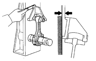
Check for bend.
Maximum bend 0.03 mm (0.00118 in.) per 100 mm (3.94 in.) If the bend is more than the maximum, replace the connecting rod sub-assembly.
-
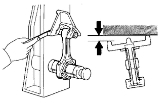
Check for twist.
Maximum twist 0.15 mm (0.00591 in.) per 100 mm (3.94 in.) If the twist is more than the maximum, replace the connecting rod sub-assembly.
-
-
-
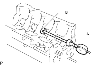
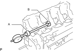
INSPECT CRANKSHAFT
-
Inspect the circle runout.
-
Place the crankshaft on V-blocks.
-
Using a dial indicator, measure the circle runout at the center journal.
Maximum circle runout 0.03 mm (0.00118 in.) If the circle runout is more than the maximum, replace the crankshaft.
-
-
Inspect the main journals.
-
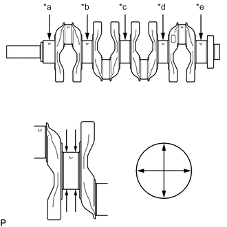
*a No. 1 *b No. 2 *c No. 3 *d No. 4 *e No. 5 Using a micrometer, measure the diameter of each main journal.
Standard Journal Diameter Item Specified Condition No. 3 Journal 59.981 to 59.994 mm (2.3615 to 2.3620 in.) Except No. 3 Journal 59.987 to 60.000 mm (2.3617 to 2.3622 in.) If the diameter is not as specified, check the oil clearance. If necessary, replace the crankshaft.
-
Check each main journal for taper and out-of- round as shown in the illustration.
Maximum taper and out-of-round 0.005 mm (0.000197 in.) If the taper and out-of-round is more than the maximum, replace the crankshaft.
-
-
Inspect the crank pins.
-
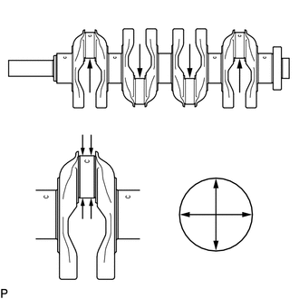
Using a micrometer, measure the diameter of each crank pin.
Standard diameter 52.989 to 53.002 mm (2.086 to 2.087 in.) If the diameter is not as specified, check the oil clearance. If necessary, replace the crankshaft.
-
Check each crank pin for taper and out-of-round as shown in the illustration.
Maximum taper and out-of-round 0.003 mm (0.000118 in.) If the taper and out-of-round is more than the maximum, replace the crankshaft.
-
-
-
INSPECT CRANKSHAFT OIL CLEARANCE
Tech Tips
-
Keep the lower crankshaft bearings and crankshaft bearing caps together.
-
Arrange the thrust washers in the correct order.
-
Keep the upper crankshaft bearings and upper thrust washers together with the cylinder block.
-
Clean each main journal and bearing.
-
Check each main journal and bearing for pitting and scratches.
If the journal or bearing is damaged, replace the bearing.
-
Install the crankshaft bearings and upper crankshaft thrust washers.
-
Place the crankshaft on the cylinder block.
-
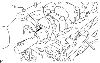
*a Plastigage Lay a strip of Plastigage across each journal.
-
Install the 5 crankshaft bearing caps with the 10 bolts.
Note
Do not turn the crankshaft.
-
Remove the 10 bolts and 5 crankshaft bearing caps.
-
Measure the Plastigage at its widest point.
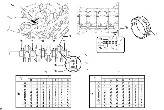
*a Plastigage *b No. 1 Journal *c No. 2 Journal *d No. 3 Journal *e No. 4 Journal *f No. 5 Journal *g Crankshaft Bearing Code *h Cylinder Block Journal Code *i Crankshaft Journal Code *j #1J, #2J, #4J, #5J *k #3J *l Bearing Code Chart Standard Oil Clearance Item Specified Condition No. 3 Journal 0.030 to 0.044 mm (0.00118 to 0.00173 in.) Other Journals 0.024 to 0.038 mm (0.000945 to 0.00150 in.) Maximum oil clearance 0.10 mm (0.00394 in.)
-
If the oil clearance is more than the maximum, replace the crankshaft bearing.
-
If replacing the cylinder block, measure the bearing standard clearance.
-
Check the cylinder block journal code and crankshaft journal code and refer to the crankshaft bearing selection chart to select a bearing size.
-
(Example) (Excluding No. 3 journal): When the cylinder block journal code is "D" and the crankshaft journal code is "4", select crankshaft bearing selection code "3" from the crankshaft bearing selection chart.
Cylinder Block Main Journal Bore Diameter Item Specified Condition Mark A 64.004 to 64.006 mm (2.51984 to 2.51992 in.) Mark B 64.007 to 64.008 mm (2.51996 to 2.51999 in.) Mark C 64.009 to 64.010 mm (2.52003 to 2.52007 in.) Mark D 64.011 to 64.012 mm (2.52011 to 2.52015 in.) Mark E 64.013 to 64.014 mm (2.52019 to 2.52023 in.) Mark F 64.015 to 64.016 mm (2.52027 to 2.52031 in.) Mark G 64.017 to 64.018 mm (2.52035 to 2.52039 in.) Mark H 64.019 to 64.020 mm (2.52043 to 2.52047 in.) Mark J 64.021 to 64.022 mm (2.52051 to 2.52055 in.) Crankshaft Journal Bore Diameter Item Specified Condition (Other Journal) Specified Condition (No. 3 Journal) Mark 0 59.999 to 60.000 mm (2.36216 to 2.36220 in.) - Mark 1 59.997 to 59.998 mm (2.36208 to 2.36212 in.) - Mark 2 59.995 to 59.996 mm (2.36200 to 2.36204 in.) - Mark 3 59.993 to 59.994 mm (2.36192 to 2.36196 in.) 59.993 to 59.994 mm (2.36192 to 2.36196 in.) Mark 4 59.991 to 59.992 mm (2.36185 to 2.36189 in.) 59.991 to 59.992 mm (2.36185 to 2.36189 in.) Mark 5 59.989 to 59.990 mm (2.36177 to 2.36181 in.) 59.989 to 59.990 mm (2.36177 to 2.36181 in.) Mark 6 59.987 to 59.988 mm (2.36169 to 2.36173 in.) 59.987 to 59.988 mm (2.36169 to 2.36173 in.) Mark 7 - 59.985 to 59.986 mm (2.36161 to 2.36165 in.) Mark 8 - 59.983 to 59.984 mm (2.36153 to 2.36157 in.) Mark 9 - 59.981 to 59.982 mm (2.36145 to 2.36149 in.) Standard Bearing Center Wall Thickness Item Specified Condition Mark 1 1.987 to 1.990 mm (0.07823 to 0.07835 in.) Mark 2 1.991 to 1.993 mm (0.07839 to 0.07846 in.) Mark 3 1.994 to 1.996 mm (0.07850 to 0.07858 in.) Mark 4 1.997 to 1.999 mm (0.07862 to 0.07870 in.) Mark 5 2.000 to 2.002 mm (0.07874 to 0.07882 in.) -
-
Completely remove the Plastigage.
-
-
INSPECT NO. 1 BALANCESHAFT
-
Inspect the diameter of the journals.
-
Using a micrometer, measure the diameter of the balanceshaft main journals.
Standard Main Journal Diameter Item Specified Condition A 37.969 to 37.985 mm (1.4948 to 1.4955 in.) B 37.449 to 37.465 mm (1.4744 to 1.4750 in.)
-
-
Inspect the diameter of the bearings.
-
Using a cylinder gauge, measure the inside diameter of the balanceshaft bearings.
Standard Bearing Inside Diameter Item Specified Condition A 38.025 to 38.045 mm (1.4970 to 1.4978 in.) B 37.525 to 37.545 mm (1.4774 to 1.4781 in.)
-
-
Inspect the oil clearance.
-
Subtract the balanceshaft main journal diameter measurement from the balanceshaft bearing inside diameter measurement.
Standard Oil Clearance Item Specified Condition A 0.040 to 0.076 mm (0.00157 to 0.00299 in.) B 0.060 to 0.096 mm (0.00236 to 0.00378 in.) Maximum oil clearance 0.15 mm (0.00591 in.) If the oil clearance is more than the maximum, replace the cylinder block and balanceshaft.
-
-
-
INSPECT NO. 2 BALANCESHAFT
-
Inspect the diameter of the journals.
-
Using a micrometer, measure the diameter of the balanceshaft main journals.
Standard Main Journal Diameter Item Specified Condition A 37.969 to 37.985 mm (1.4948 to 1.4955 in.) B 37.449 to 37.465 mm (1.4744 to 1.4750 in.)
-
-
Inspect the diameter of the bearings.
-
Using a cylinder gauge, measure the inside diameter of the balanceshaft bearings.
Standard Bearing Inside Diameter Item Specified Condition A 38.025 to 38.045 mm (1.4970 to 1.4978 in.) B 37.525 to 37.545 mm (1.4774 to 1.4781 in.)
-
-
Inspect the oil clearance.
-
Subtract the balanceshaft main journal diameter measurement from the balanceshaft bearing inside diameter measurement.
Standard Oil Clearance Item Specified Condition A 0.040 to 0.076 mm (0.00157 to 0.00299 in.) B 0.060 to 0.096 mm (0.00236 to 0.00378 in.) Maximum oil clearance 0.15 mm (0.00591 in.) If the oil clearance is more than the maximum, replace the cylinder block and balanceshaft.
-
-
-
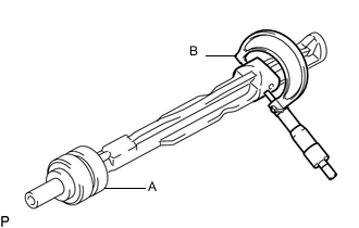
INSPECT NO. 1 OIL NOZZLE SUB-ASSEMBLY
-
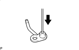
Push Push the check valve with a pin to check if it is stuck.
If the check valve is stuck, replace the No. 1 oil nozzle sub-assembly.
-
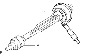
Push the check valve with a pin to check if it moves smoothly.
If the check valve does not move smoothly, clean or replace the No. 1 oil nozzle sub-assembly.
-
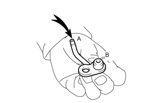
Air Blow air into A. Check that air does not leak from B.
If air leaks, clean or replace the No. 1 oil nozzle sub-assembly.
-
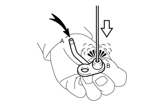
Air 
Push Push the check valve while blowing air into A. Check that air passes through B.
If air does not pass through B, clean or replace the No. 1 oil nozzle sub-assembly.
-
-
INSPECT CRANKSHAFT BEARING CAP SET BOLT
-
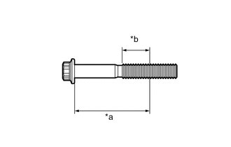
*a Distance *b Measuring Area Using a vernier caliper, measure the diameter of the most elongated threads in the measuring area.
Distance 64 mm (2.52 in.) Standard diameter 10.76 to 10.97 mm (0.424 to 0.432 in.) Minimum diameter 10.66 mm (0.420 in.) If the diameter is less than the minimum, replace the crankshaft bearing cap set bolt.
-
-
INSPECT CONNECTING ROD BOLT
-
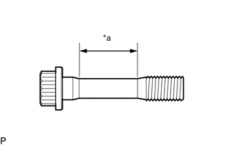
*a Tension Portion Using a vernier caliper, measure the tension portion diameter of the bolt.
Standard diameter 7.2 to 7.3 mm (0.283 to 0.287 in.) Minimum diameter 7.0 mm (0.276 in.) If the diameter is less than the minimum, replace the connecting rod bolt.
-