MONOLITHIC CONVERTER(w/ DPF) INSTALLATION
PROCEDURE
-
INSTALL EXHAUST MANIFOLD CONVERTER SUB-ASSEMBLY
-
Set a new gasket and the exhaust manifold converter sub-assembly to the turbocharger sub-assembly.
-
Temporarily install the exhaust pipe support stay to the cylinder block sub-assembly and exhaust manifold converter sub-assembly with the 3 bolts.
-
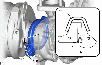
*1 Exhaust Pipe Clamp *2 Exhaust Manifold Converter *3 Turbocharger Sub-assembly *4 Gasket Install a new exhaust pipe clamp to the exhaust manifold converter sub-assembly with a new nut.
- Torque:
- 18 N*m { 184 kgf*cm, 13 ft.*lbf }
-
Tighten the 3 bolts and install the exhaust pipe support stay to the cylinder block sub-assembly and exhaust manifold converter sub-assembly.
- Torque:
- 38 N*m { 387 kgf*cm, 28 ft.*lbf }
-
-
INSTALL NO. 2 EXHAUST PIPE SUPPORT STAY
-
Install the No. 2 exhaust pipe support stay to the cylinder block sub-assembly and exhaust manifold converter sub-assembly with the bolt and 2 new nuts.
- Torque:
- 38 N*m { 387 kgf*cm, 28 ft.*lbf }
-
-
INSTALL NO. 1 TURBO INSULATOR
-
Install the No. 1 turbo insulator to the exhaust manifold and turbocharger sub-assembly with the 3 bolts.
- Torque:
- 12 N*m { 122 kgf*cm, 9 ft.*lbf }
-
-
INSTALL NO. 1 EXHAUST MANIFOLD HEAT INSULATOR
-
Install the No. 1 exhaust manifold heat insulator to the exhaust manifold with the 3 bolts.
- Torque:
- 12 N*m { 122 kgf*cm, 9 ft.*lbf }
-
-
INSTALL AIR FUEL RATIO SENSOR
-
INSTALL UPPER ARM BUSH HEAT INSULATOR
-
Install the upper arm bush heat insulator to the body with the 2 bolts.
- Torque:
- 32 N*m { 326 kgf*cm, 24 ft.*lbf }
-
-
INSTALL NO. 2 INTERMEDIATE SHAFT SUB-ASSEMBLY (for RHD)
-
INSTALL ENGINE COVER BRACKET
-
Install the engine cover bracket to the cylinder head sub-assembly with the 2 bolts.
- Torque:
- 21 N*m { 214 kgf*cm, 15 ft.*lbf }
-
Attach the 2 clamps and connect the engine wire to the cylinder head sub-assembly.
-
-
INSTALL PIPE CLAMP
-
Install the pipe clamp to the engine cover bracket with the 3 bolts.
- Torque:
- 10 N*m { 102 kgf*cm, 7 ft.*lbf }
-
-
TEMPORARILY INSTALL NO. 2 VACUUM PIPE
-
Install a new clamp to the pipe clamp.
-
Temporarily install the No. 2 vacuum pipe to the exhaust manifold converter sub-assembly.
-
-
TEMPORARILY INSTALL NO. 1 VACUUM PIPE
-
Temporarily install the No. 1 vacuum pipe to the exhaust manifold converter sub-assembly.
-
Install a new clamp to the No. 1 vacuum pipe and No. 2 vacuum pipe with the nut.
- Torque:
- 6.0 N*m { 61 kgf*cm, 53 in.*lbf }
-
-
TIGHTEN NO. 2 VACUUM PIPE
-
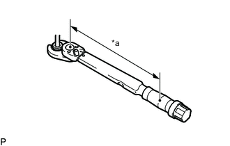
*a Torque Wrench Fulcrum Length Using a 17 mm union nut wrench, tighten the No. 2 vacuum pipe.
- Torque:
- Specified tightening torque
- 48 N*m { 489 kgf*cm, 35 ft.*lbf }
Tech Tips
-
Calculate the torque wrench reading when changing the fulcrum length of the torque wrench.
-
When using a union nut wrench (fulcrum length of 30 mm (1.18 in.)) + torque wrench (fulcrum length of 255 mm (10.0 in.)): 42.9 N*m (437 kgf*cm, 32 ft.*lbf)
-
-
TIGHTEN NO. 1 VACUUM PIPE
-
*a Torque Wrench Fulcrum Length Using a 17 mm union nut wrench, tighten the No. 1 vacuum pipe.
- Torque:
- Specified tightening torque
- 48 N*m { 489 kgf*cm, 35 ft.*lbf }
Tech Tips
-
Calculate the torque wrench reading when changing the fulcrum length of the torque wrench.
-
When using a union nut wrench (fulcrum length of 30 mm (1.18 in.)) + torque wrench (fulcrum length of 255 mm (10.0 in.)): 42.9 N*m (437 kgf*cm, 32 ft.*lbf)
-
-
INSTALL EXHAUST GAS TEMPERATURE SENSOR
-
INSTALL DIFFERENTIAL PRESSURE SENSOR
-
INSTALL AIR CLEANER CASE SUB-ASSEMBLY
-
INSTALL AIR CLEANER FILTER ELEMENT SUB-ASSEMBLY
-
INSTALL AIR CLEANER CAP AND HOSE
-
INSTALL FRONT FENDER SEAL
-
for 2WD:
Install the front fender seal to the body with 5 new clips.
-
for 4WD and Pre-Runner:
Install the front fender seal to the body with 6 new clips.
-
-
INSTALL FUEL ADDITION INJECTOR ASSEMBLY
-
INSTALL FRONT EXHAUST PIPE ASSEMBLY
-
BLEED AIR FROM FUEL SYSTEM
-
ADD ENGINE COOLANT
-
INSPECT FOR COOLANT LEAK