STEREO JACK ADAPTER ASSEMBLY INSTALLATION
CAUTION / NOTICE / HINT
Tech Tips
-
Use the same procedure for RHD and LHD vehicles.
-
The procedure listed below is for LHD vehicles.
PROCEDURE
-
INSTALL RADIO WIRE
-
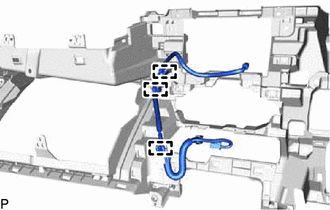
Attach the clamps to install the radio wire.
-
-
INSTALL LOWER INSTRUMENT PANEL SUB-ASSEMBLY
-
INSTALL NO. 1 STEREO JACK ADAPTER ASSEMBLY
-
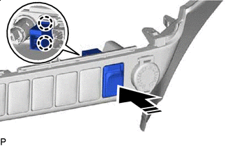

Install in this Direction Attach the claws to install the No. 1 stereo jack adapter assembly.
-
-
INSTALL LOWER INSTRUMENT COVER SUB-ASSEMBLY
-
INSTALL FRONT CONSOLE BOX (w/o Console Box Lid)
-
INSTALL FRONT CONSOLE BOX COVER (w/o Console Box Lid)
-
INSTALL UPPER CONSOLE PANEL SUB-ASSEMBLY (w/ Console Box Lid)
-
INSTALL SHIFT LEVER KNOB SUB-ASSEMBLY
-
INSTALL AIR CONDITIONING CONTROL ASSEMBLY (for Automatic Air Conditioning System)
-
CONNECT AIR MIX DAMPER CONTROL CABLE SUB-ASSEMBLY (for Manual Air Conditioning System)
-
CONNECT AIR INLET DAMPER CONTROL CABLE SUB-ASSEMBLY (for Manual Air Conditioning System)
-
CONNECT DEFROSTER DAMPER CONTROL CABLE SUB-ASSEMBLY (for Manual Air Conditioning System)
-
INSTALL INTEGRATION PANEL SUB-ASSEMBLY WITH AIR CONDITIONING CONTROL ASSEMBLY (for Manual Air Conditioning System)
-
INSTALL AIR INLET DAMPER CONTROL LEVER (for Manual Air Conditioning System)
-
INSTALL CONTROL KNOB SUB-ASSEMBLY (for Manual Air Conditioning System)
-
CONNECT AIR INLET DAMPER CONTROL CABLE SUB-ASSEMBLY (for Manual Cooler System)
-
CONNECT DEFROSTER DAMPER CONTROL CABLE SUB-ASSEMBLY (for Manual Cooler System)
-
INSTALL INTEGRATION PANEL SUB-ASSEMBLY WITH AIR CONDITIONING CONTROL ASSEMBLY (for Manual Cooler System)
-
INSTALL AIR INLET DAMPER CONTROL LEVER (for Manual Cooler System)
-
INSTALL CONTROL KNOB SUB-ASSEMBLY (for Manual Cooler System)
-
INSTALL INSTRUMENT CLUSTER FINISH PANEL ASSEMBLY
-
INSTALL STEERING WHEEL ASSEMBLY
-
CONNECT CABLE TO NEGATIVE BATTERY TERMINAL
Note
When disconnecting the cable, some systems need to be initialized after the cable is reconnected Click here.