UPPER INSTRUMENT PANEL INSTALLATION
CAUTION / NOTICE / HINT
Use the same procedure for RHD and LHD vehicles.
The procedure listed below is for LHD vehicles.
PROCEDURE
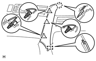
INSTALL INSTRUMENT PANEL SAFETY PAD SUB-ASSEMBLY
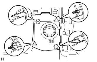
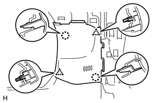
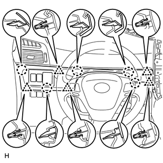
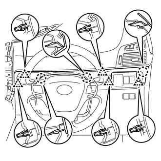
Securely attach the 5 guides, 4 claws and 2 clips of the instrument panel safety pad to the vehicle body.
Install the instrument panel safety pad with the 3 screws <B>.
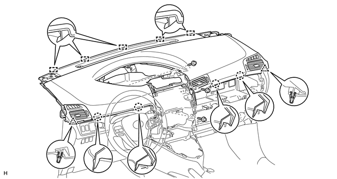
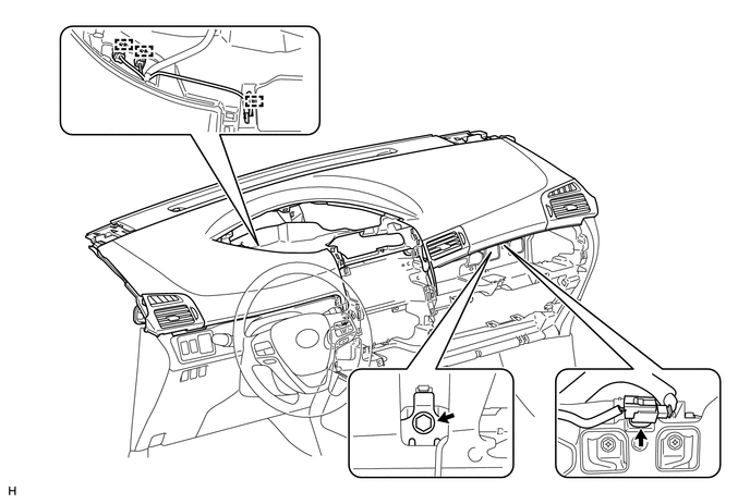
Install the passenger airbag bolt <A>.
20 N*m
204 kgf*cm
15 ft.*lbf
Connect the connector and clamps.
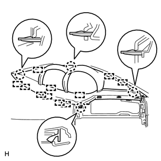
INSTALL NO. 1 INSTRUMENT PANEL SPEAKER PANEL SUB-ASSEMBLY
for 4 Speakers:
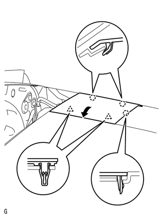
Set the 2 claws on the side of the No. 1 instrument panel speaker panel towards the front of the vehicle in place and using them as pivot points, lower the No. 1 instrument panel speaker panel in the direction indicated by the arrow in the illustration, and then attach the claws and clips to the instrument panel to install the No. 1 instrument panel speaker panel.
-
for 6 Speakers:
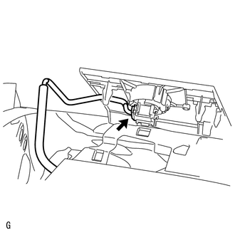
Connect the speaker connector.
-
Set the 2 claws on the side of the No. 1 instrument panel speaker panel towards the front of the vehicle in place and using them as pivot points, lower the No. 1 instrument panel speaker panel in the direction indicated by the arrow in the illustration, and then attach the claws and clips to the instrument panel to install the No. 1 instrument panel speaker panel.
INSTALL NO. 2 INSTRUMENT PANEL SPEAKER PANEL SUB-ASSEMBLY
Tip:Use the same procedure described for the No. 1 instrument panel speaker panel.
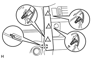
INSTALL NO. 1 SWITCH HOLE BASE
w/ Entry and Start System:
Connect the connector.
Attach the 2 claws and 2 clips to install the No. 1 switch hole base.
-
w/o Entry and Start System:
Attach the 2 claws and 2 clips to install the No. 1 switch hole base.
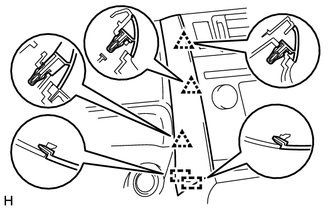
INSTALL NO. 2 SWITCH HOLE BASE
for LHD:
Attach the 5 claws and 5 clips to install the No. 2 switch hole base.
-
for RHD:
Attach the 3 claws and 5 clips to install the No. 2 switch hole base.
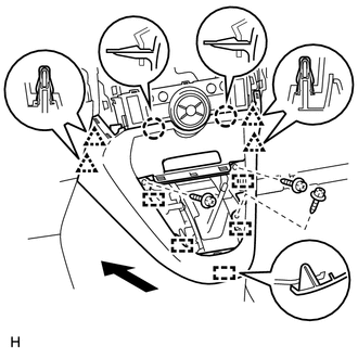
INSTALL LOWER CENTER INSTRUMENT PANEL FINISH PANEL (for Manual Transaxle)
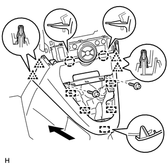
for Automatic Air Conditioning System:
Attach the 2 claws, 4 clips and 5 guides to install the lower center instrument panel finish panel.
Install the 2 screws <C>.
-
for Manual Air Conditioning System:
Attach the 4 clips, 2 claws and 5 guides to install the lower center instrument panel finish panel.
Install the 2 screws <C>.
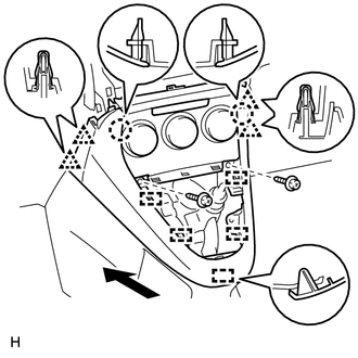
INSTALL LOWER CENTER INSTRUMENT PANEL FINISH PANEL (except Manual Transaxle)
for Automatic Air Conditioning System:
Attach the 2 claws, 4 clips and 5 guides to install the lower center instrument panel finish panel.
Install the 3 screws <C>.
-
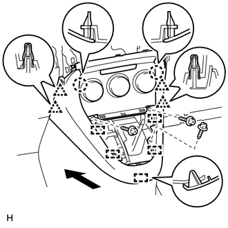
for Manual Air Conditioning System:
Attach the 4 clips, 2 claws and 5 guides to install the lower center instrument panel finish panel.
Install the 3 screws <C>.
INSTALL SHIFTING HOLE COVER (for Manual Transaxle)
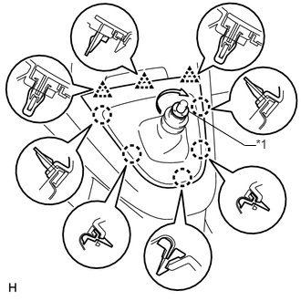
Attach the 5 claws and 3 clips to install the shifting hole cover.
Install the knob spring.
Install the T washer and twist it in the direction indicated by the arrow.
Table 1. Text in Illustration *1
T Washer
INSTALL POSITION INDICATOR HOUSING ASSEMBLY (except Manual Transaxle)
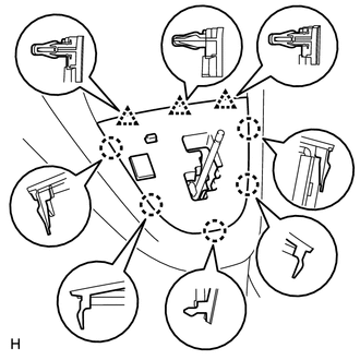
Connect the connector.
Attach the 5 claws and 3 clips to install the position indicator housing.
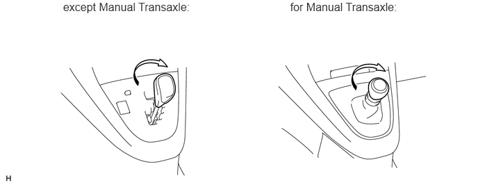
INSTALL SHIFT LEVER KNOB SUB-ASSEMBLY
Install the shift lever knob and twist it in the direction indicated by the arrow.
INSTALL STEREO OPENING COVER WITH BRACKET (w/o Audio)
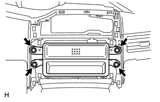
Install the stereo opening cover with the 4 bolts.
INSTALL RADIO RECEIVER ASSEMBLY (w/ Audio, for Radio Receiver Type)
INSTALL RADIO AND DISPLAY RECEIVER ASSEMBLY (w/ Audio, for Radio and Display Type)
INSTALL CENTER INSTRUMENT CLUSTER FINISH PANEL SUB-ASSEMBLY (w/o Audio, for Radio and Display Type)
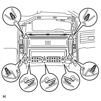
Attach the 4 clips, 3 claws and 3 guides to install the center instrument cluster finish panel.
INSTALL COMBINATION METER ASSEMBLY
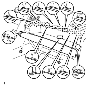
INSTALL INSTRUMENT CLUSTER FINISH PANEL ASSEMBLY
Attach the 11 guides and 4 claws to install the instrument cluster finish panel.
INSTALL CENTER INSTRUMENT PANEL REGISTER ASSEMBLY
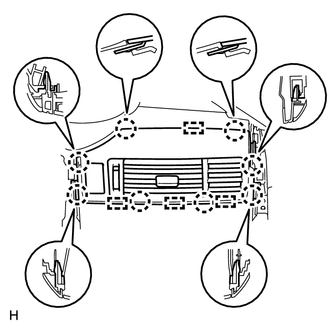
Connect the connector.
Attach the 8 claws and 4 guides to install the center instrument panel register.
INSTALL INSTRUMENT PANEL FINISH PANEL END RH
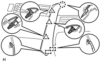
for Automatic Air Conditioning System:
Attach the 3 clips, claw and 2 guides to install the instrument panel finish panel end RH.
-
for Manual Air Conditioning System:
Attach the 3 clips, claw and guide to install the instrument panel finish panel end RH.
INSTALL INSTRUMENT PANEL FINISH PANEL END LH
-
for Automatic Air Conditioning System:
Attach the 3 clips and 2 guides to install the instrument panel finish panel end LH.
-
for Manual Air Conditioning System:
Attach the 3 clips and guide to install the instrument panel finish panel end LH.
-
INSTALL GLOVE COMPARTMENT DOOR SUB-ASSEMBLY
Connect the connector.
Attach the 7 claws and 5 guides to install the glove compartment door.
Install the 2 screws.
INSTALL FRONT PILLAR GARNISH LH
INSTALL FRONT PILLAR GARNISH RH
INSTALL FRONT DOOR OPENING TRIM WEATHERSTRIP LH
INSTALL FRONT DOOR OPENING TRIM WEATHERSTRIP RH
INSTALL COWL SIDE TRIM BOARD LH
INSTALL COWL SIDE TRIM BOARD RH
INSTALL FRONT DOOR SCUFF PLATE LH
INSTALL FRONT DOOR SCUFF PLATE RH
CONNECT CABLE TO NEGATIVE BATTERY TERMINAL
Note:When disconnecting the cable, some systems need to be initialized after the cable is reconnected (Click here).
CHECK SRS WARNING LIGHT
Check the SRS warning light (Click here).