ECD SYSTEM(for Swirl Control Valve), Diagnostic DTC:P007C and P007D
| DTC Code | DTC Name |
|---|---|
| P007C | Charge Air Cooler Temperature Sensor Circuit Low Bank 1 |
| P007D | Charge Air Cooler Temperature Sensor Circuit High Bank 1 |
DESCRIPTION
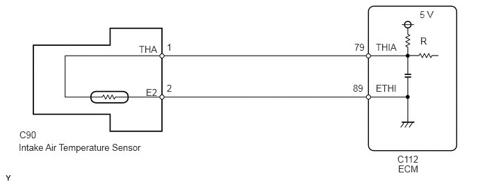
The intake air temperature sensor is located on the charge-air pipe between the intercooler assembly and the throttle valve. The intake air temperature sensor detects the temperature of the intake air compressed by the turbocharger and cooled by the intercooler assembly.
A temperature-dependent electrical resistor is used for temperature sensing. The circuit contains a voltage divider where the resistance can be measured depending on the temperature. A temperature is converted using a characteristic curve specific to the sensor. An NTC resistor (NTC) is installed in the intake air temperature sensor, whose resistance value drops when the temperature increases. The resistance changes between 76 kΩ and 88 Ω depending on the temperature, which corresponds to a temperature between -40°C (-40°F) and 120°C (248°F).
DTC No. |
DTC Detection Condition |
Trouble Area |
|---|---|---|
P007C |
Intake air temperature sensor output voltage is 0.2 V or less for 0.6 seconds. (3 trip detection logic) |
|
DTC No. |
DTC Detection Condition |
Trouble Area |
|---|---|---|
P007D |
Intake air temperature sensor output voltage is 4.95 V or more for 0.6 seconds. (3 trip detection logic) |
|
DTC No. |
Data List |
|---|---|
P007C P007D |
Intake Air Temp (Turbo) |
WIRING DIAGRAM
CAUTION / NOTICE / HINT
When replacing the ECM, the ECM needs Registration and Initialization (Click here).
When the ECM must be replaced, before replacing the ECM, perform the "Learning Values Save" function using the GTS. Then after installing the new ECM, perform all of the initialization/registrations for the "Learning Values Write" function by following the instructions shown on the GTS display.
Read freeze frame data using the GTS. Freeze frame data records the engine condition when malfunctions are detected. When troubleshooting, freeze frame data can help determine if the vehicle was moving or stationary, if the engine was warmed up or not, and other data from the time the malfunction occurred.
PROCEDURE
READ VALUE USING GTS (INTAKE AIR TEMP (TURBO))
Connect the GTS to the DLC3.
Turn the ignition switch to ON and turn the GTS on.
Enter the following menus: Powertrain / Engine and ECT / Data List / Intake Air Temp (Turbo).
Read the value.
OK
Same as actual intake air temperature.
Table 2. Result Result
Proceed to
-40°C (-40°F) or less
A
120°C (248°F) or more
B
Same as actual intake air temperature
C
Tip:If there is an open circuit, the GTS indicates -40°C (-40°F) or less.
If there is a short circuit, the GTS indicates 120°C (248°F) or more.
READ VALUE USING GTS (CHECK FOR SHORT IN WIRE HARNESS)Click here
CONFIRM WHETHER MALFUNCTION HAS BEEN SUCCESSFULLY REPAIREDClick here
READ VALUE USING GTS (CHECK FOR OPEN IN WIRE HARNESS)
Disconnect the intake air temperature sensor connector.
Connect terminals C90-1 (THA) and C90-2 (E2) of the intake air temperature sensor wire harness side connector.
Connect the GTS to the DLC3.
Turn the ignition switch to ON and turn the GTS on.
Enter the following menus: Powertrain / Engine and ECT / Data List / Intake Air Temp (Turbo).
Standard value
120°C (248°F) or more
CONFIRM GOOD CONNECTION TO SENSOR. IF OK, REPLACE INTAKE AIR TEMPERATURE SENSORClick here
CHECK HARNESS AND CONNECTOR (INTAKE AIR TEMPERATURE SENSOR - ECM)
Disconnect the intake air temperature sensor connector.
Disconnect the ECM connector.
Measure the resistance according to the value(s) in the table below.
Standard Resistance
Tester Connection
Condition
Specified Condition
C90-1 (THA) - C112-79 (THIA)
Always
Below 1 Ω
C90-2 (E2) - C112-89 (ETHI)
Always
Below 1 Ω
CONFIRM GOOD CONNECTION TO ECM. IF OK, REPLACE ECMClick here
REPAIR OR REPLACE HARNESS OR CONNECTORClick here
READ VALUE USING GTS (CHECK FOR SHORT IN WIRE HARNESS)
Disconnect the intake air temperature sensor connector.
Connect the GTS to the DLC3.
Turn the ignition switch to ON and turn the GTS on.
Enter the following menus: Powertrain / Engine and ECT / Data List / Intake Air Temp (Turbo).
Standard value
-40°C (-40°F) or less
REPLACE INTAKE AIR TEMPERATURE SENSORClick here
CHECK HARNESS AND CONNECTOR (INTAKE AIR TEMPERATURE SENSOR - ECM)
Disconnect the intake air temperature sensor connector.
Disconnect the ECM connector.
Measure the resistance according to the value(s) in the table below.
Standard Resistance
Tester Connection
Condition
Specified Condition
C90-1 (THA) or C112-79 (THIA) - Body ground
Always
10 kΩ or higher
REPAIR OR REPLACE HARNESS OR CONNECTORClick here
REPLACE ECM
Replace the ECM (Click here).
CONFIRM WHETHER MALFUNCTION HAS BEEN SUCCESSFULLY REPAIREDClick here
CONFIRM GOOD CONNECTION TO SENSOR. IF OK, REPLACE INTAKE AIR TEMPERATURE SENSOR
Replace the intake air temperature sensor (Click here).
CONFIRM WHETHER MALFUNCTION HAS BEEN SUCCESSFULLY REPAIREDClick here
REPAIR OR REPLACE HARNESS OR CONNECTOR
Repair or replace the harness or connector.
CONFIRM WHETHER MALFUNCTION HAS BEEN SUCCESSFULLY REPAIREDClick here
CONFIRM GOOD CONNECTION TO ECM. IF OK, REPLACE ECM
Replace the ECM (Click here).
CONFIRM WHETHER MALFUNCTION HAS BEEN SUCCESSFULLY REPAIREDClick here
REPLACE INTAKE AIR TEMPERATURE SENSOR
Replace the intake air temperature sensor (Click here).
CONFIRM WHETHER MALFUNCTION HAS BEEN SUCCESSFULLY REPAIRED
Connect the GTS to the DLC3.
Turn the ignition switch to ON and turn the GTS on.
Clear the DTCs (Click here).
Turn the ignition switch off and wait for 60 seconds or more [A].
Perform road test [B].
Repeat [A] and [B] for the number of trips detected.
Enter the following menus: Powertrain / Engine and ECT / Trouble Codes.
Confirm that the DTC is not output again.
END