СИСТЕМА ECD СИСТЕМА ДИАГНОСТИКИ
-
DESCRIPTION
-

Description for M-OBD
-
When troubleshooting Multiplex OBD (M-OBD) vehicles, the only difference from the usual troubleshooting procedure is to connect the intelligent tester to the vehicle and read various data output from the vehicle's ECM.
-
The vehicle's on-board computer illuminates the Malfunction Indicator Lamp (MIL) on the instrument panel when the computer detects a malfunction in the computer itself or in drive system components. In addition to illuminating the MIL when a malfunction is detected, the applicable Diagnostic Trouble Codes (DTCs) are recorded in the ECM memory Click here. When the malfunction does not reoccur, the MIL is illuminated until the ignition switch is turned OFF, and then the MIL is not illuminated when the ignition switch is turned ON but the DTCs remain recorded in the ECM memory.
-
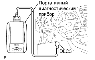
To check the DTC, connect the intelligent tester to the Data Link Connector 3 (DLC3) on the vehicle or read the number of blinks of the MIL when the TC and CG terminals on the DLC3 are connected. The intelligent tester also enables you to erase the DTCs, activate several actuators, check freeze frame data and various forms of engine data (for operating instructions, see the intelligent tester instruction book).
-
-
-
NORMAL MODE AND CHECK MODE
The diagnosis system operates in the normal mode during normal vehicle use. It also has a check mode for technicians to simulate malfunction symptoms and perform troubleshooting. Most DTCs use 2-trip detection logic to prevent an erroneous detection, and ensure a thorough malfunction detection. By switching the ECM to the check mode using the intelligent tester when troubleshooting, a technician can cause the MIL to light up for a malfunction that is only detected once or momentarily (intelligent tester only) (see "2-TRIP DETECTION LOGIC" below).
-
2-TRIP DETECTION LOGIC
When a logic malfunction is first detected, the malfunction is temporarily stored in the ECM memory (1st trip). If the same malfunction is detected again during the second drive test, this second detection causes the MIL to light up (2nd trip) (however, the ignition switch must be turned OFF between the 1st trip and 2nd trip).
-
FREEZE FRAME DATA
The ECM records vehicle and driving condition information as freeze frame data the moment a DTC is stored. When troubleshooting, freeze frame data can be helpful in determining whether the vehicle was running or stopped, whether the engine was warmed up or not, whether the air/fuel ratio was lean or rich, as well as other data recorded at the time of a malfunction.
-
DLC3 (Data Link Connector 3)
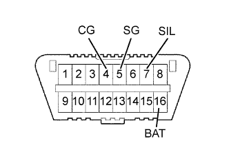
The vehicle's ECM uses the ISO 14230 (M-OBD) communication protocol. The terminal arrangement of DLC3 complies with ISO 15031-03 and matches the ISO 14230 format.
Symbols (Terminal No.) Terminal Description Condition Specified Condition SIL (7) - SG (5) Bus "+" line During transmission Pulse generation CG (4) - Body ground Chassis ground Always Below 1 Ω SG (5) - Body ground Signal ground Always Below 1 Ω BAT (16) - Body ground Battery positive Always 9 to 14 V If the result is not as specified, the DLC3 may have a malfunction. Repair or replace the harness and connector.
Tech Tips
Connect the cable of the intelligent tester to the DLC3, turn the ignition switch ON and attempt to use the tester. If the display indicates that a communication error has occurred, there is a problem either with the vehicle or with the tester.
-
If communication is normal when the tester is connected to another vehicle, inspect the DLC3 on the original vehicle.
-
If communication is not possible when the tester is connected to another vehicle, the problem is probably in the tester itself. Consult the Service Department listed in the intelligent tester's operator's manual.
-
-
BATTERY VOLTAGE
If the voltage is below 11 V, recharge the battery before proceeding.
-
MIL (Malfunction Indicator Lamp)
-
The MIL illuminates when the ignition switch is ON and the engine is not running.
Tech Tips
If the MIL is not illuminated, check the MIL circuit (refer to MIL Circuit Click here.
-
The MIL should turn off when the engine is started. If the MIL remains illuminated, the diagnosis system has detected a malfunction or abnormality in the system.
-