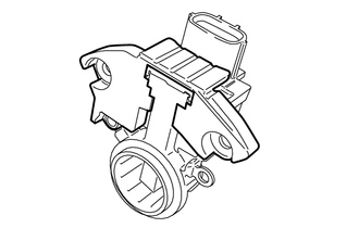
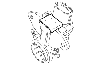
GENERATOR DISASSEMBLY

PROCEDURE
-
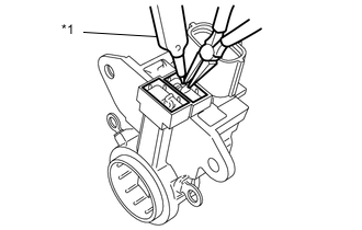
REMOVE GENERATOR REAR END COVER
-
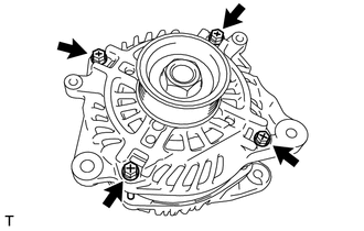
Remove the 4 through bolts.
-
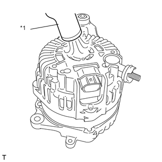
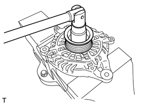
Text in Illustration *1 Heat gun Using the heat gun, heat the generator rear end cover.
Heating Temperature Item Temperature Generator Rear End Cover 50 to 60°C (122 to 140°F) -
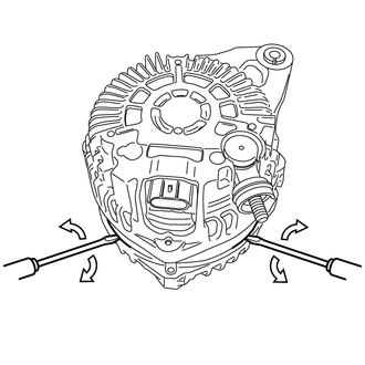
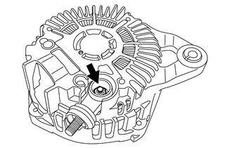
Insert the 2 screw drivers, and remove the generator rear end cover as shown in the illustration.
-
-
REMOVE GENERATOR PULLEY
-
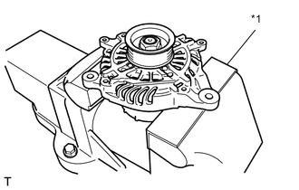
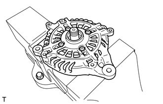
Text in Illustration *1 Aluminium plate Mount the generator in a vise between aluminum plates.
-
Remove the nut and generator pulley.
-
-
REMOVE GENERATOR DRIVE END FRAME ASSEMBLY
-
Remove the generator drive end frame assembly from the generator rotor assembly.
-
-
REMOVE GENERATOR DRIVE END FRAME BEARING
-
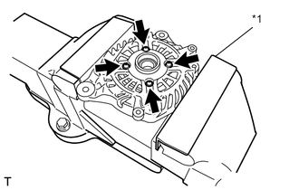
Mount the generator drive end frame assembly in a vise between aluminum plates.
-
Remove the 4 bolts and bearing retainer.
Text in Illustration *1 Aluminium plate -
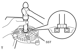
Using SST and a hammer, tap out the bearing.
- SST
- 09950-60010 ( 09951-00250 )
- 09950-70010 ( 09951-07100 )
-
-
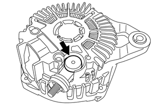
REMOVE GENERATOR ROTOR BEARING
-
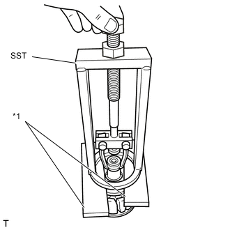
Text in Illustration *1 Wooden block Set the SST to the generator rotor assembly between wooden blocks.
- SST
- 09387-00041
-
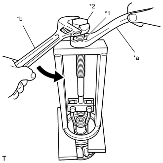
Text in Illustration *1 SST Nut *2 SST Bolt *a Hold *b Turn Hold the SST nut, and turn the SST bolt to remove the generator rotor bearing.
-
-
REMOVE GENERATOR COIL ASSEMBLY
-
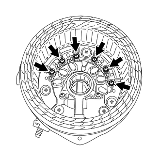
Remove the 6 bolts and generator coil assembly.
-
-
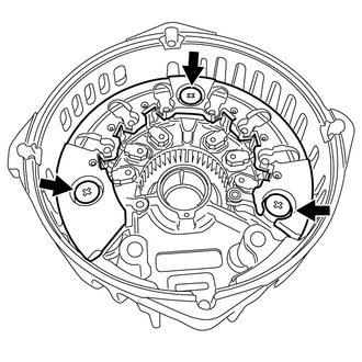
REMOVE GENERATOR BRUSH HOLDER ASSEMBLY
-
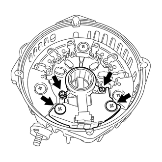
Remove the 4 bolts and generator brush holder assembly.
-
-
REMOVE BRUSH
-
Remove the cover A from the brush holder assembly.
-
Remove the cover B from the brush holder assembly.
-
Text in Illustration *1 Soldering iron Using a soldering iron, separate the 2 brushes from the brush holder assembly.
-
-
REMOVE GENERATOR HOLDER WITH RECTIFIER
-
Remove the terminal cover.
-
Remove the nut and the terminal.
-
Remove the 3 bolts and the generator holder with rectifier.
-