CYLINDER HEAD INSPECTION

PROCEDURE
-
INSPECT CYLINDER HEAD SUB-ASSEMBLY
-
Visually check that there are no cracks, scratches or other damage.
-
Using a dye penetrant, check the important sections for fissures.
-
Check that there are no signs of gas leak or water leak on gasket attachment surfaces.
-
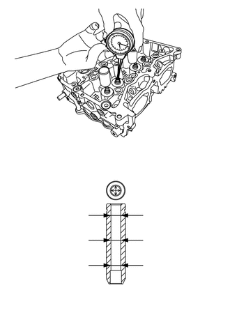
Using a precision straightedge and a feeler gauge, measure the surfaces that contact the cylinder block for warpage.
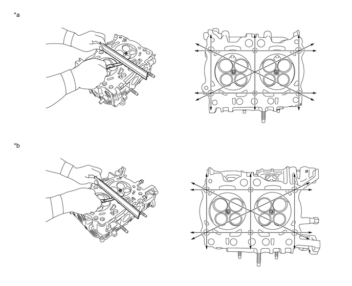
Text in Illustration *a for Bank 1 *b for Bank 2 Maximum warpage 0.020 mm (0.000787 in.) Allowable minimum cylinder head height 98.4 mm (3.874 in.) Standard cylinder head height 98.5 mm (3.878 in.) If the warpage is more than the maximum, correct the surface by grinding it or replace the cylinder head sub-assembly.
Tech Tips
-
Measurement should be performed at a temperature of 20°C (68°F).
-
If the cylinder head sub-assembly bolt tightening torques and tightening angles are uneven, cylinder head sub-assembly warpage may occur. During installation, make sure that tightening torques and tightening angles are correctly obtained.
-
If the cylinder head sub-assembly is replaced, hand-lap the valve and valve seat with an abrasive compound.
-
-
-
INSPECT INTAKE VALVE
-
Check the valve flange and valve stem for damage, wear or deformation.
-
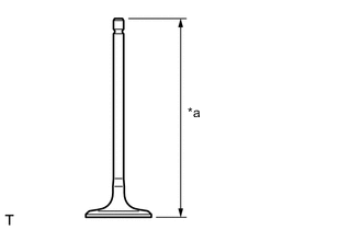
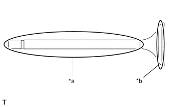
Text in Illustration *a Overall Length Using a vernier caliper, measure the overall length of the valve.
Standard overall length 104.95 mm (4.13 in.) -
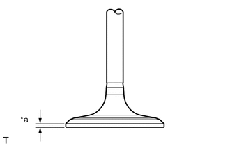
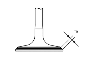
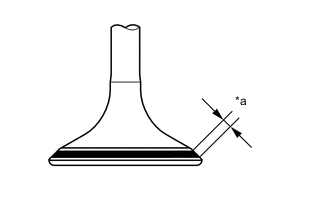
Text in Illustration *a Margin thickness Using a vernier caliper, measure the valve head margin thickness.
Standard margin thickness 0.8 to 1.2 mm (0.0315 to 0.0472 in.) If the margin thickness is not as specified, replace the valve.
Tech Tips
-
It is possible to differentiate between the intake valve and the exhaust valve by their overall length.
-
If the valve is replaced, hand-lap the valve and valve seat with an abrasive compound.
-
-
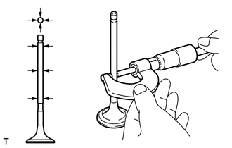
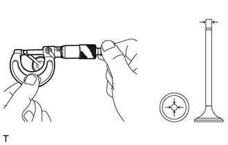
Using a micrometer, measure the diameter of the valve stem.
Standard valve stem diameter 5.455 to 5.470 mm (0.2148 to 0.2154 in.) If the valve stem diameter is not as specified, replace the valve.
Tech Tips
-
Measurement should be performed at a temperature of 20°C (68°F).
-
Measure the valve stem diameter at the 6 locations as shown in the illustration, and take the minimum value.
-
If the valve is replaced, hand-lap the valve and valve seat with an abrasive compound.
-
-
-
INSPECT EXHAUST VALVE
-
Check the valve flange and valve stem for damage, wear or deformation.
-
Text in Illustration *a Overall Length Using a vernier caliper, measure the overall length of the valve.
Standard overall length 97.57 mm (3.84 in.) -
Text in Illustration *a Margin thickness Using a vernier caliper, measure the valve head margin thickness.
Standard margin thickness 1.0 to 1.4 mm (0.039 to 0.055 in.) If the margin thickness is not as specified, replace the valve.
Tech Tips
-
It is possible to differentiate between the intake valve and the exhaust valve by their overall length.
-
If the valve is replaced, hand-lap the valve and valve seat with an abrasive compound.
-
-
Using a micrometer, measure the diameter of the valve stem.
Standard valve stem diameter 5.445 to 5.460 mm (0.21437 to 0.21496 in.) If the valve stem diameter is not as specified, replace the valve.
Tech Tips
-
Measurement should be performed at a temperature of 20°C (68°F).
-
Measure the valve stem diameter at the 6 locations as shown in the illustration, and take the minimum value.
-
If the valve is replaced, hand-lap the valve and valve seat with an abrasive compound.
-
-
-
INSPECT VALVE GUIDE BUSH OIL CLEARANCE
-
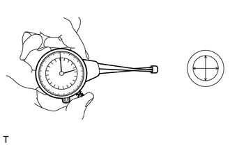
Using a caliper gauge, measure the inside diameter of the valve guide bush.
Standard valve guide bush inside diameter 5.500 to 5.512 mm (0.21654 to 0.21701 in.) If the inside diameter is not as specified, replace the valve guide bush.
Tech Tips
-
Measurement should be performed at a temperature of 20°C (68°F).
-
Measure the inside diameter of the valve guide bush at the 6 locations as shown in the illustration, and take the maximum value.
-
-
Calculate the clearance between the valve guide bush and valve stem.
Standard Oil Clearance Item Specified Condition Intake 0.030 to 0.057 mm (0.00118 to 0.00224 in.) Exhaust 0.040 to 0.067 mm (0.00157 to 0.00264 in.) If the clearance between valve guide bush and valve stem is more the standard, replace the valve guide bush or valve, whichever shows the greater amount of wear or damage.
Tech Tips
-
Subtract the valve stem diameter measurement from the inside diameter measurement of the valve guide bush.
-
If the valve is replaced, hand-lap the valve and valve seat with an abrasive compound.
-
-
-
INSPECT VALVE ADJUSTING SHIM CLEARANCE
-
Visually check the valve adjusting shim for damage.
-
Using a micrometer, measure the valve stem end diameter.
Standard valve stem end diameter Item Specified Condition Intake 5.455 to 5.470 mm (0.21476 to 0.21535 in.) Exhaust 5.445 to 5.460 mm (0.21437 to 0.21496 in.) If the valve stem end diameter is not as specified, replace the valve.
Tech Tips
-
Measurement should be performed at a temperature of 20°C (68°F).
-
Measure the valve stem end diameter at the 2 locations as shown in the illustration, and take the minimum value.
-
If the valve is replaced, hand-lap the valve and valve seat with an abrasive compound.
-
-
Using a caliper gauge, measure the inside diameter of the valve adjusting shim.
Standard valve adjusting shim inside diameter 5.500 to 5.560 mm (0.21654 to 0.21890 in.) If the inside diameter is not as specified, replace the valve adjusting shim.
Tech Tips
-
Measurement should be performed at a temperature of 20°C (68°F).
-
Measure the inside diameter of the valve adjusting shim at the 2 locations as shown in the illustration, and take the maximum value.
-
If the valve adjusting shim needs to be replaced, check the valve clearance and select a suitable one.
-
-
Calculate the clearance between the valve adjusting shim and valve stem end.
Standard Oil Clearance Item Specified Condition Intake 0.030 to 0.105 mm (0.00118 to 0.00413 in.) Exhaust 0.040 to 0.115 mm (0.00157 to 0.00453 in.) If the clearance between valve adjusting shim and valve stem end exceeds the standard, replace the valve adjusting shim or valve, whichever shows the greater amount of wear or damage.
Tech Tips
-
Subtract the valve stem end diameter measurement from the inside diameter measurement of the valve adjusting shim.
-
If the valve is replaced, hand-lap the valve and valve seat with an abrasive compound.
-
If the valve adjusting shim needs to be replaced, check the valve clearance and select a suitable one.
-
-
-
INSPECT INTAKE VALVE SEATS
-
Visually check the valve seat for damage or deformation.
-
Clean the valve and valve seat.
-
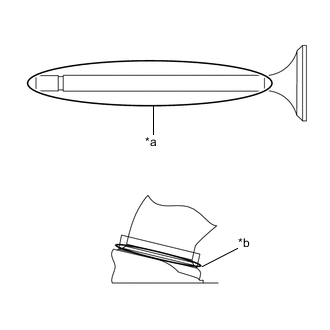
Text in Illustration *a Valve stem *b Valve face Apply a light coat of engine oil to the valve stem, and a light coat of Prussian blue uniformly to the valve face.
-
Insert the valve, and without rotating the valve, lightly press the valve face against the valve seat, and then pull it out.
-
Using a vernier caliper, measure the width of the contact face shown in the illustration.
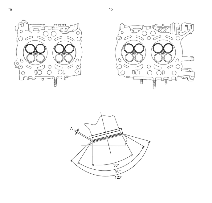
Text in Illustration *a for Bank 1 *b for Bank 2 Standard width (A) 0.8 to 1.6 mm (0.032 to 0.063 in.) If the width is not as specified, repair the valve seat with a cutter.
Tech Tips
-
Measure the width of the Prussian blue adhering to the valve seat.
-
If the Prussian blue is not continually adhered on the valve seat, hand-lap the valve and valve seat with an abrasive compound.
-
If the Prussian blue is still not continually adhered on the valve seat after lapping, repair the valve seat with a cutter.
-
-
Completely remove the Prussian blue from the valve and valve seat.
-
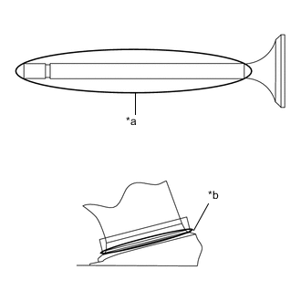
Text in Illustration *a Valve stem *b Contact face Apply a light coat of engine oil to the valve stem, and a light coat of Prussian blue uniformly to the valve seat face.
-
Insert the valve, and without rotating the valve, lightly press the valve face against the valve seat, and then pull it out.
-
Text in Illustration *a Contact face location Check the location of the contact face shown in the illustration.
Standard contact face location Middle of the valve face at all circumference If the seat contact is not in the middle of the valve face, repair the valve seat with a cutter.
Tech Tips
Check the location of the Prussian blue adhering to the valve face.
-
Completely remove the Prussian blue from the valve and valve seat.
-
-
INSPECT EXHAUST VALVE SEATS
-
Visually check the valve seat for damage or deformation.
-
Clean the valve and valve seat.
-
Text in Illustration *a Valve stem *b Valve face Apply a light coat of engine oil to the valve stem, and a light coat of Prussian blue uniformly to the valve face.
-
Insert the valve, and without rotating the valve, lightly press the valve face against the valve seat, and then pull it out.
-
Using a vernier caliper, measure the width of the contact face shown in the illustration.
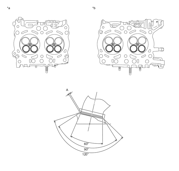
Text in Illustration *a for Bank 1 *b for Bank 2 Standard width (A) 1.1 to 1.7 mm (0.043 to 0.067 in.) If the width is not as specified, repair the valve seat with a cutter.
Tech Tips
-
Measure the width of the Prussian blue adhering to the valve seat.
-
If the Prussian blue is not continually adhered on the valve seat, hand-lap the valve and valve seat with an abrasive compound.
-
If the Prussian blue is still not continually adhered on the valve seat after lapping, repair the valve seat with a cutter.
-
-
Completely remove the Prussian blue from the valve and valve seat.
-
Text in Illustration *a Valve stem *b Contact face Apply a light coat of engine oil to the valve stem, and a light coat of Prussian blue uniformly to the valve seat face.
-
Insert the valve, and without rotating the valve, lightly press the valve face against the valve seat, and then pull it out.
-
Text in Illustration *a Contact face location Check the location of the contact face shown in the illustration.
Standard contact face location Middle of the valve face at all circumference If the seat contact is not in the middle of the valve face, repair the valve seat with a cutter.
Tech Tips
Check the location of the Prussian blue adhering to the valve face.
-
Completely remove the Prussian blue from the valve and valve seat.
-
-
INSPECT VALVE SPRING
-
Visually check the valve spring for damage or deformation.
-
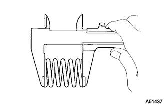
Using a vernier caliper, measure the free length of the valve spring.
Standard free length 41.06 mm (1.617 in.) If the free length is not as specified, replace the spring.
Tech Tips
Measurement should be performed at a temperature of 20°C (68°F).
-
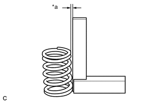
Text in Illustration *a Deviation Using a steel square, measure the deviation of the valve spring.
Maximum deviation Less than 1.8 mm (0.0710 in.) Maximum angle 2.5° If the result is not as specified, replace the valve spring.
Tech Tips
-
Measurement should be performed at a temperature of 20°C (68°F).
-
To measure deviation of the valve spring, stand the valve spring on a level surface and measure its deviation at the top of the valve spring using a steel square.
-
-