EXHAUST MANIFOLD INSTALLATION
PROCEDURE
INSTALL NO. 1 MANIFOLD CONVERTER INSULATOR
Install the No. 1 manifold converter insulator with the 4 bolts.
12 N*m
122 kgf*cm
9 ft.*lbf
INSTALL EXHAUST MANIFOLD CONVERTER SUB-ASSEMBLY
-
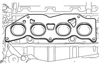
Install a new gasket to the cylinder head.
-
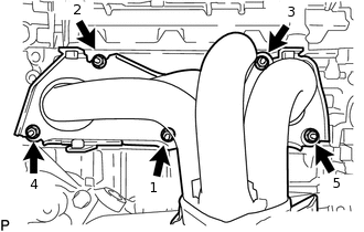
Temporarily install the exhaust manifold converter sub-assembly with the 5 nuts.
Tighten the 5 nuts in the sequence shown in the illustration.
35 N*m
357 kgf*cm
26 ft.*lbf
-
INSTALL NO. 2 EXHAUST MANIFOLD HEAT INSULATOR
Install the No. 2 exhaust manifold heat insulator with the 2 bolts.
12 N*m
122 kgf*cm
9 ft.*lbf
INSTALL NO. 1 EXHAUST MANIFOLD HEAT INSULATOR
Install the No. 1 exhaust manifold heat insulator with the 4 bolts.
12 N*m
122 kgf*cm
9 ft.*lbf
INSTALL NO. 2 MANIFOLD STAY
Install the No. 2 manifold stay with the bolt and nut.
43 N*m
438 kgf*cm
32 ft.*lbf
INSTALL MANIFOLD STAY
Install the manifold stay with the bolt and nut.
43 N*m
438 kgf*cm
32 ft.*lbf
INSTALL AIR FUEL RATIO SENSOR (for Bank 1 Sensor 1)
INSTALL RADIATOR HOSE HOSE CLAMP
INSTALL ENGINE OIL LEVEL DIPSTICK GUIDE
INSTALL FRONT EXHAUST PIPE SUB-ASSEMBLY
-
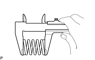
Using a vernier caliper, measure the free length of the compression spring.
Minimum length
41.5 mm (1.63 in.)
If the length is less than the minimum, replace the compression spring.
Using a wire brush, remove any foreign matter from the gasket installation surface.
-
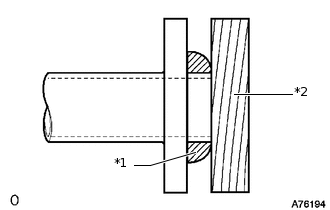
*1
Gasket
*2
Wooden Block
Using a plastic-faced hammer and wooden block, tap in a new gasket until its surface is flush with the exhaust manifold converter sub-assembly.
Note:Be sure to install the gasket so that it faces the correct direction.
Do not reuse the gasket.
Do not damage the gasket.
When connecting the front exhaust pipe assembly, do not push in the gasket with the front exhaust pipe assembly.
Install a new gasket to the front exhaust pipe sub-assembly.
Install the front exhaust pipe sub-assembly with the 2 compression springs and 4 bolts.
43 N*m
438 kgf*cm
32 ft.*lbf
Connect the heated oxygen sensor connector.
-
INSTALL GENERATOR ASSEMBLY
INSPECT FOR EXHAUST GAS LEAK