FORWARD RECOGNITION CAMERA SYSTEM TERMINALS OF ECU
CHECK FORWARD RECOGNITION CAMERA

Disconnect the Q17 forward recognition camera connector.
Note:DTCs may be output when connectors are disconnected during inspection. Therefore, be sure to clear the DTCs using the GTS once the inspection has been completed.
Do not apply excessive force to the Q17 forward recognition camera connector.
Measure the voltage and resistance according to the value(s) in the table below.
Terminal No. (Symbol)
Wiring Color
Terminal Description
Condition
Specified Condition
Q17-7 (IGB) - Body ground
GR - Body ground
Power source
Power switch on (IG)
11 to 14 V
Power switch off
Below 1 V
Q17-10 (GND) - Body ground
W-B - Body ground
Ground
Always
Below 1 Ω
Tip:If the result is not as specified, there may be a malfunction on the wire harness side.
Reconnect the Q17 forward recognition camera connector.
w/ Camera Heater:
Measure the voltage according to the value(s) in the table below.
Terminal No. (Symbol)
Wiring Color
Terminal Description
Condition
Specified Condition
Q17-1 (HTR) - Body ground
R - Body ground
Forward recognition with heater hood sub-assembly operation signal
Power switch on (IG), and the forward recognition with heater hood sub-assembly operating
Below 1 V
Power switch on (IG), and the forward recognition with heater hood sub-assembly not operating
11 to 14 V
Check for pulses according to the value(s) in the table below.
Terminal No. (Symbol)
Wiring Color
Terminal Description
Condition
Specified Condition
Q17-5 (CA1P) - Q17-10 (GND)
G - W-B
CAN communication signal
Power switch on (IG)
Pulse generation
(See waveform 1)
Q17-11 (CA1N) - Q17-10 (GND)
LG - W-B
CAN communication signal
Power switch on (IG)
Pulse generation
(See waveform 2)
Q17-6 (CANH) - Q17-10 (GND)
L - W-B
CAN communication signal
Power switch on (IG)
Pulse generation
(See waveform 1)
Q17-12 (CANL) - Q17-10 (GND)
W - W-B
CAN communication signal
Power switch on (IG)
Pulse generation
(See waveform 2)
-
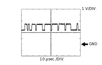
WAVEFORM 1
CAN communication signal
Item
Content
Terminal Name
Between Q17-5 (CA1P) and Q17-10 (GND)
Between Q17-6 (CANH) and Q17-10 (GND)
Tester Range
1 V/DIV., 10 μsec./DIV.
Condition
Power switch on (IG)
Tip:The waveform varies depending on the CAN communication signal.
-
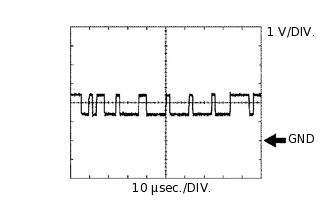
WAVEFORM 2
CAN communication signal
Item
Content
Terminal Name
Between Q17-11 (CA1N) and Q17-10 (GND)
Between Q17-12 (CANL) and Q17-10 (GND)
Tester Range
1 V/DIV., 10 μsec./DIV.
Condition
Power switch on (IG)
Tip:The waveform varies depending on the CAN communication signal.