TELEMATICS SYSTEM SYSTEM DESCRIPTION
DESCRIPTION
ERA-GLONASS provides 2 services: Automatic Emergency Call and Manual Emergency Call.
If the vehicle is involved in an accident, the telematics system will make an automatic emergency call to a Public Safety Answering Point (PSAP) and transmit the vehicle location, determined by a GNSS satellite, and vehicle information. After receiving an emergency call from the vehicle, depending on the situation, a PSAP operator may immediately contact emergency services.
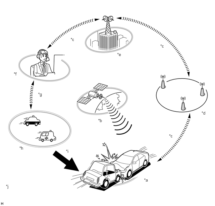
*a
Emergency Call Service
*b
GNSS Satellite
*c
Cellular Phone Line
*d
Cellular Phone Base Station
*e
Mobile Network Operator (MNO) or Mobile Virtual Network Operator (MVNO)
*f
Public Safety Answering Point (PSAP)
*g
Public Fixed Line
*h
Emergency Vehicle
*i
Public safety authorities such a police or fire department
*j
The illustrations shown are examples only and may differ from the actual service.
FUNCTION OF MAIN COMPONENTS
Component
Function
Map Light Assembly
Manual (SOS) Switch
Sends a switch signal to the telematics transceiver when pressed. (When a test call or manual emergency call is performed.)
LED Indicator Light
Green
Illuminates for 2 seconds after the power switch is turned on (IG) and the manual (SOS) switch indicator (red) has illuminated for 10 seconds.
Turns on when the system is operating normally.
Blinks during an emergency call.
Blinks during test mode.
Blinks 5 times when entering test mode (the manual (SOS) switch indicator (green) blinks at the same time).
Red
Illuminates for 10 seconds after the power switch is turned on (IG).
Blinks when an emergency call fails.
Turns off when the system is operating normally.
Illuminates when the mobilephone battery needs to be replaced.
Illuminates when the DTCs are stored.
Blinks 5 times when entering test mode (the manual (SOS) switch indicator (red) blinks at the same time).
Map Light Assembly
Telephone Microphone Assembly
Sends the microphone voice signal to the telematics transceiver.
No. 1 Amplifier Antenna Assembly
Sends and receives data and voice signals used for emergency calls via a communication network.
Receives GPS and GLONASS radio signals and sends them to the radio and display receiver assembly.*
Telematics Transceiver
Uses the No. 1 amplifier antenna assembly to send and receive data and voice signals used for emergency calls via a communication network.
-
Sends the received voice signal to the vehicle speakers.
Receives the sent voice signal from the telephone microphone assembly.
Sends a mute signal to the radio and display assembly.* (The audio system is automatically muted during an emergency call.)
Sends vehicle location information to the PSAP.
Conducts self-diagnosis every time the power switch is turned on (IG) and after an automatic emergency call or manual emergency call is made.
Mobilephone Battery
When an automatic emergency call is performed, provides power to the telematics transceiver.
When a manual emergency call is made, is not used as the power source.
Airbag Sensor Assembly
Sends an activation signal to the telematics transceiver when the airbags deploy. (An automatic emergency call is made.)
*: for Radio and Display Type
MAYDAY ID OUTLINE
The telematics transceiver functions as the emergency call service device to perform emergency calls.
The telematics transceiver has serial numbers (IMEI, ICCID) which can be used to identify the individual device when servicing.
-
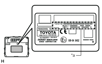
*a
IMEI, ICCID
The IMEI and ICCID are printed on the label attached to the telematics transceiver.
COMMUNICATION SYSTEM
CAN Communication Outline
The telematics system uses CAN communication between the telematics transceiver and ECUs.
DIAGNOSTIC FUNCTION OUTLINE
The telematics system has a diagnostic function (the result will be displayed on GTS).