FRONT POWER SEAT CONTROL SYSTEM One-touch Walk-in Function does not Operate
DESCRIPTION
-
When the reclining remote control lever sub-assembly is operated and the front seatback frame sub-assembly is folded forward, each limit switch is turned on and sends a signal to the position control ECU and switch assembly (driver seat) or position control ECU and switch assembly (front passenger seat) according to the condition of the front seatback frame sub-assembly.
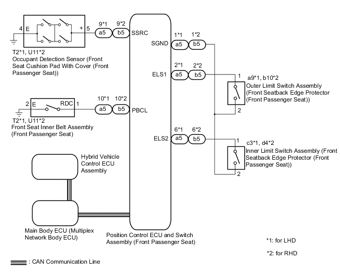
WIRING DIAGRAM
-
for Driver Seat
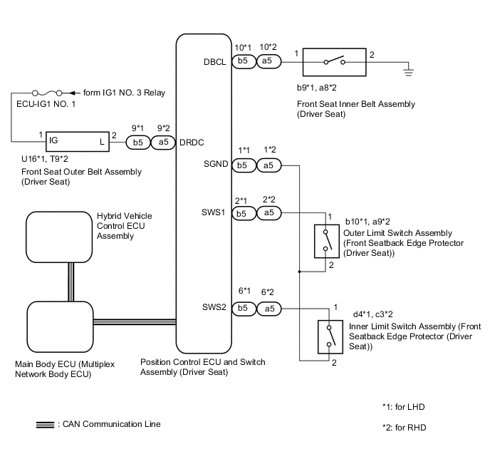
-
for Front Passenger Seat
CAUTION / NOTICE / HINT
Note
-
The front power seat control system uses the CAN communication system. First, confirm that there are no malfunctions in the CAN communication system. Refer to How to Proceed with Troubleshooting.
-
Before replacing the main body ECU (multiplex network body ECU), refer to Service Bulletin.
PROCEDURE
-
CHECK FRONT POWER SEAT OPERATION
-
Check that each function of the power seat operates normally by using the front power seat switch (driver seat) or front power seat switch (front passenger seat).
Result Result Proceed to Driver power seat functions do not operate A Front passenger power seat functions do not operate B
B 
READ VALUE USING GTS (P SEAT BUCKLE SWITCH) Click here
A 
-
-
CHECK SEAT BELT TENSION REDUCER SYSTEM
-
Check the seat belt tension reducer system.
OK Seat belt tension reducer system is normal. Result Proceed to OK NG
NG 
GO TO SEAT BELT TENSION REDUCER SYSTEM Click here
OK
-
-
CHECK FOR DTC
-
Perform "DTC Output Confirmation Operation" procedure.
-
Check for DTCs.
Powertrain > Hybrid Control > Trouble CodesOK P0705-757 is not output. Result Proceed to OK NG
NG
GO TO HYBRID CONTROL SYSTEM Click here
OK
-
-
READ VALUE USING GTS (SHIFT SW POSITION)
-
Connect the GTS to the DLC3.
-
Turn the power switch on (IG).
-
Turn the GTS on.
-
Enter the following menus: Body Electrical / Driver Seat / Data List.
-
Read the Data List according to the display on the GTS.
Body Electrical > Driver Seat > Data ListTester Display Measurement Item Range Normal Condition Diagnostic Note Shift SW Position Park state signal Shift P or Shift Other Shift P: Shift lever in P
Shift Other: Shift lever in a position other than P
-
Body Electrical > Driver Seat > Data ListTester Display Shift SW Position OK The GTS display changes correctly in response to the shift lever position. Result Proceed to OK NG
NG
REPLACE POSITION CONTROL ECU AND SWITCH ASSEMBLY (DRIVER SEAT) Click here
OK
-
-
READ VALUE USING GTS (OPERATION LEVER STATE AND SLIDE FRONT OPERATION PERMITTED)
-
Connect the GTS to the DLC3.
-
Turn the power switch on (IG).
-
Turn the GTS on.
-
Enter the following menus: Body Electrical / Driver Seat / Data List.
-
Read the Data List according to the display on the GTS.
Body Electrical > Driver Seat > Data ListTester Display Measurement Item Range Normal Condition Diagnostic Note Operation Lever State Reclining remote control lever sub-assembly state Lock or Unlock Lock: Reclining remote control lever sub-assembly locked
Unlock: Reclining remote control lever sub-assembly unlocked
- Slide Front Operation Permitted Forward operation permission state NO or YES NO: Not permitted
YES: Permitted
-
Body Electrical > Driver Seat > Data ListTester Display Operation Lever State Slide Front Operation Permitted Result Result Proceed to The value of each Data List item change accordingly. A The value of the Data List item "Operation Lever State"not change according to the operation of the reclining remote control lever sub-assembly. B The value of the Data List item "Slide Front Operation Permitted" does not change according to the forward operation permission state. C The value of each Data List item does not change. D
A
USE SIMULATION METHOD TO CHECK Click here
C
INSPECT OUTER LIMIT SWITCH ASSEMBLY (FRONT SEATBACK EDGE PROTECTOR (DRIVER SEAT)) Click here
D
CHECK HARNESS AND CONNECTOR (POSITION CONTROL ECU AND SWITCH ASSEMBLY (DRIVER SEAT) - OUTER LIMIT SWITCH ASSEMBLY (FRONT SEATBACK EDGE PROTECTOR (DRIVER SEAT)) Click here
B
-
-
INSPECT INNER LIMIT SWITCH ASSEMBLY (FRONT SEATBACK EDGE PROTECTOR (DRIVER SEAT))
-
Remove the inner limit switch assembly (front seatback edge protector (driver seat)).
-
Inspect the inner limit switch assembly (front seatback edge protector (driver seat)).
Result Proceed to OK NG
NG
REPLACE INNER LIMIT SWITCH ASSEMBLY (FRONT SEATBACK EDGE PROTECTOR (DRIVER SEAT)) Click here
OK
-
-
CHECK CHECK HARNESS AND CONNECTOR (POSITION CONTROL ECU AND SWITCH ASSEMBLY (DRIVER SEAT) - INNER LIMIT SWITCH ASSEMBLY (FRONT SEATBACK EDGE PROTECTOR DRIVER SEAT (DRIVER))
-
Disconnect the b5*1 or a5*2 position control ECU and switch assembly (driver seat) connector.
-
*1: for LHD
-
*2: for RHD
-
-
Disconnect the d4*1 or c3*2 inner limit switch assembly (front seatback edge protector (driver seat)) connector.
-
*1: for LHD
-
*2: for RHD
-
-
Measure the resistance according to the value(s) in the table below.
Standard Resistance for LHD Tester Connection Condition Specified Condition b5-6 (SWS2) - d4-1 Always Below 1 Ω b5-6 (SWS2) or d4-1 - Body ground Always 10 kΩ or higher b5-1 (SGND) - d4-2 Always Below 1 Ω b5-1 (SGND) or d4-2 - Body ground Always 10 kΩ or higher for RHD Tester Connection Condition Specified Condition a5-6 (SWS2) - c3-1 Always Below 1 Ω a5-6 (SWS2) or c3-1 - Body ground Always 10 kΩ or higher a5-1 (SGND) - c3-2 Always Below 1 Ω a5-1 (SGND) or c3-2 - Body ground Always 10 kΩ or higher Result Proceed to OK NG
OK
REPLACE POSITION CONTROL ECU AND SWITCH ASSEMBLY (DRIVER SEAT) Click here
NG
REPAIR OR REPLACE HARNESS OR CONNECTOR
-
-
INSPECT OUTER LIMIT SWITCH ASSEMBLY (FRONT SEATBACK EDGE PROTECTOR (DRIVER SEAT))
-
Remove the outer limit switch assembly (front seatback edge protector (driver seat)).
-
Inspect the outer limit switch assembly (front seatback edge protector (driver seat)).
Result Proceed to OK NG
NG
REPLACE OUTER LIMIT SWITCH ASSEMBLY (FRONT SEATBACK EDGE PROTECTOR (DRIVER SEAT)) Click here
OK
-
-
CHECK HARNESS AND CONNECTOR (POSITION CONTROL ECU AND SWITCH ASSEMBLY (DRIVER SEAT) - OUTER LIMIT SWITCH ASSEMBLY (FRONT SEATBACK EDGE PROTECTOR (DRIVER SEAT))
-
Disconnect the b5*1 or a5*2 position control ECU and switch assembly (driver seat) connector.
-
*1: for LHD
-
*2: for RHD
-
-
Disconnect the b10*1 or a9*2 outer limit switch assembly (front seatback edge protector (driver seat)) connector.
-
*1: for LHD
-
*2: for RHD
-
-
Measure the resistance according to the value(s) in the table below.
Standard Resistance for LHD Tester Connection Condition Specified Condition b5-2 (SWS1) - b10-1 Always Below 1 Ω b5-2 (SWS1) or b10-1 - Body ground Always 10 kΩ or higher b5-1 (SGND) - b10-2 Always Below 1 Ω b5-1 (SGND) or b10-2 - Body ground Always 10 kΩ or higher for RHD Tester Connection Condition Specified Condition a5-2 (SWS1) - a9-1 Always Below 1 Ω a5-2 (SWS1) or a9-1 - Body ground Always 10 kΩ or higher a5-1 (SGND) - a9-2 Always Below 1 Ω a5-1 (SGND) or a9-2 - Body ground Always 10 kΩ or higher Result Proceed to OK NG
OK
REPLACE POSITION CONTROL ECU AND SWITCH ASSEMBLY (DRIVER SEAT) Click here
NG
REPAIR OR REPLACE HARNESS OR CONNECTOR
-
-
CHECK HARNESS AND CONNECTOR (POSITION CONTROL ECU AND SWITCH ASSEMBLY (DRIVER SEAT) - OUTER LIMIT SWITCH ASSEMBLY (FRONT SEATBACK EDGE PROTECTOR (DRIVER SEAT))
-
Disconnect the b5*1 or a5*2 position control ECU and switch assembly (driver seat) connector.
-
*1: for LHD
-
*2: for RHD
-
-
Disconnect the b10*1 or a9*2 outer limit switch assembly (front seatback edge protector (driver seat)) connector.
-
*1: for LHD
-
*2: for RHD
-
-
Measure the resistance according to the value(s) in the table below.
Standard Resistance for LHD Tester Connection Condition Specified Condition b5-1 (SGND) - b10-2 Always Below 1 Ω b5-1 (SGND) or b10-2 - Body ground Always 10 kΩ or higher for RHD Tester Connection Condition Specified Condition a5-1 (SGND) - a9-2 Always Below 1 Ω a5-1 (SGND) or a9-2 - Body ground Always 10 kΩ or higher Result Proceed to OK NG
OK
REPLACE POSITION CONTROL ECU AND SWITCH ASSEMBLY (DRIVER SEAT) Click here
NG
REPAIR OR REPLACE HARNESS OR CONNECTOR
-
-
READ VALUE USING GTS (P SEAT BUCKLE SWITCH)
-
Connect the GTS to the DLC3.
-
Turn the power switch on (IG).
-
Turn the GTS on.
-
Enter the following menus: Body Electrical / Passenger Seat / Data List.
-
Read the Data List according to the display on the GTS.
Body Electrical > Passenger Seat > Data ListTester Display Measurement Item Range Normal Condition Diagnostic Note P Seat Buckle Switch Front passenger seat belt buckle switch ON or OFF ON: Front passenger seat belt fastened
OFF: Front passenger seat belt unfastened
-
Body Electrical > Passenger Seat > Data ListTester Display P Seat Buckle Switch OK On the GTS screen, ON or OFF is displayed accordingly. Result Proceed to OK NG
NG
INSPECT FRONT SEAT INNER BELT ASSEMBLY (FRONT PASSENGER SEAT) Click here
OK
-
-
READ VALUE USING GTS (OCCUPANT SENSOR)
-
Connect the GTS to the DLC3.
-
Turn the power switch on (IG).
-
Turn the GTS on.
-
Enter the following menus: Body Electrical / Passenger Seat / Data List.
-
Read the Data List according to the display on the GTS.
Body Electrical > Passenger Seat > Data ListTester Display Measurement Item Range Normal Condition Diagnostic Note Occupant Sensor Occupant sensor condition ON or OFF ON: Occupant Sensor on
OFF: Occupant Sensor off
-
Body Electrical > Passenger Seat > Data ListTester Display Occupant Sensor OK On the GTS screen, ON or OFF is displayed accordingly. Result Proceed to OK NG
NG
INSPECT OCCUPANT DETECTION SENSOR (FRONT SEAT CUSHION PAD WITH COVER (FRONT PASSENGER SEAT)) Click here
OK
-
-
CHECK FOR DTC
-
Perform "DTC Output Confirmation Operation" procedure.
-
Check for DTCs.
Powertrain > Hybrid Control > Trouble CodesOK P0705-757 is not output. Result Proceed to OK NG
NG
GO TO HYBRID CONTROL SYSTEM Click here
OK
-
-
READ VALUE USING GTS (SHIFT P POSITION STATE)
-
Connect the GTS to the DLC3.
-
Turn the power switch on (IG).
-
Turn the GTS on.
-
Enter the following menus: Body Electrical / Passenger Seat / Data List.
-
Read the Data List according to the display on the GTS.
Body Electrical > Passenger Seat > Data ListTester Display Measurement Item Range Normal Condition Diagnostic Note Shift SW Position Park state signal Shift P or Shift Other Shift P: Shift lever in P
Shift Other: Shift lever in a position other than P
-
Body Electrical > Passenger Seat > Data ListTester Display Shift SW Position OK The GTS display changes correctly in response to the shift lever position. Result Proceed to OK NG
NG
REPLACE POSITION CONTROL ECU AND SWITCH ASSEMBLY (FRONT PASSENGER SEAT) Click here
OK
-
-
READ VALUE USING GTS (OPERATION LEVER STATE AND SLIDE FRONT OPERATION PERMITTED)
-
Connect the GTS to the DLC3.
-
Turn the power switch on (IG).
-
Turn the GTS on.
-
Enter the following menus: Body Electrical / Passenger Seat / Data List.
-
Read the Data List according to the display on the GTS.
Body Electrical > Passenger Seat > Data ListTester Display Measurement Item Range Normal Condition Diagnostic Note Operation Lever State Reclining remote control lever sub-assembly state Lock or Unlock Lock: Reclining remote control lever sub-assembly locked
Unlock: Reclining remote control lever sub-assembly unlocked
- Slide Front Operation Permitted Forward operation permission state NO or YES NO: Not permitted
YES: Permitted
-
Body Electrical > Passenger Seat > Data ListTester Display Operation Lever State Slide Front Operation Permitted Result Result Proceed to The value of each Data List item change accordingly. A The value of the Data List item "Operation Lever State" does not change according to the operation of the reclining remote control lever sub-assembly. B The value of the Data List item "Slide Front Operation Permitted" does not change according to the forward operation permission state. C The value of each Data List item does not change. D
A
USE SIMULATION METHOD TO CHECK Click here
C
INSPECT OUTER LIMIT SWITCH ASSEMBLY (FRONT SEATBACK EDGE PROTECTOR (FRONT PASSENGER SEAT)) Click here
D
CHECK HARNESS AND CONNECTOR (POSITION CONTROL ECU AND SWITCH ASSEMBLY (FRONT PASSENGER SEAT) - OUTER LIMIT SWITCH ASSEMBLY (FRONT SEATBACK EDGE PROTECTOR (FRONT PASSENGER SEAT)) Click here
B
-
-
INSPECT INNER LIMIT SWITCH ASSEMBLY (FRONT SEATBACK EDGE PROTECTOR (FRONT PASSENGER SEAT))
-
Remove the inner limit switch assembly (front seatback edge protector (front passenger seat)).
-
Inspect the inner limit switch assembly (front seatback edge protector (front passenger seat)).
Result Proceed to OK NG
NG
REPLACE INNER LIMIT SWITCH ASSEMBLY (FRONT SEATBACK EDGE PROTECTOR (FRONT PASSENGER SEAT)) Click here
OK
-
-
CHECK HARNESS AND CONNECTOR (POSITION CONTROL ECU AND SWITCH ASSEMBLY (FRONT PASSENGER SEAT) - INNER LIMIT SWITCH ASSEMBLY (FRONT SEATBACK EDGE PROTECTOR (FRONT PASSENGER SEAT))
-
Disconnect the a5*1 or b5*2 position control ECU and switch assembly (front passenger seat) connector.
-
*1: for LHD
-
*2: for RHD
-
-
Disconnect the c3*1 or d4*2 inner limit switch assembly (front seatback edge protector (front passenger seat)) connector.
-
*1: for LHD
-
*2: for RHD
-
-
Measure the resistance according to the value(s) in the table below.
Standard Resistance for LHD Tester Connection Condition Specified Condition a5-6 (ELS2) - c3-1 Always Below 1 Ω a5-6 (ELS2) or c3-1 - Body ground Always 10 kΩ or higher a5-1 (SGND) - c3-2 Always Below 1 Ω a5-1 (SGND) or c3-2 - Body ground Always 10 kΩ or higher for RHD Tester Connection Condition Specified Condition b5-6 (ELS2) - d4-1 Always Below 1 Ω b5-6 (ELS2) or d4-1 - Body ground Always 10 kΩ or higher b5-1 (SGND) - d4-2 Always Below 1 Ω b5-1 (SGND) or d4-2 - Body ground Always 10 kΩ or higher Result Proceed to OK NG
OK
REPLACE POSITION CONTROL ECU AND SWITCH ASSEMBLY (FRONT PASSENGER SEAT) Click here
NG
REPAIR OR REPLACE HARNESS OR CONNECTOR
-
-
INSPECT OUTER LIMIT SWITCH ASSEMBLY (FRONT SEATBACK EDGE PROTECTOR (FRONT PASSENGER SEAT))
-
Remove the outer limit switch assembly (front seatback edge protector).
-
Inspect the outer limit switch assembly (front seatback edge protector).
Result Proceed to OK NG
NG
REPLACE OUTER LIMIT SWITCH ASSEMBLY (FRONT SEATBACK EDGE PROTECTOR) Click here
OK
-
-
CHECK HARNESS AND CONNECTOR (POSITION CONTROL ECU AND SWITCH ASSEMBLY (FRONT PASSENGER SEAT) - OUTER LIMIT SWITCH ASSEMBLY (FRONT SEATBACK EDGE PROTECTOR (FRONT PASSENGER SEAT))
-
Disconnect the a5*1 or b5*2 position control ECU and switch assembly (front passenger seat) connector.
-
*1: for LHD
-
*2: for RHD
-
-
Disconnect the a9*1 or b10*2 outer limit switch assembly (front seatback edge protector (front passenger seat)) connector.
-
*1: for LHD
-
*2: for RHD
-
-
Measure the resistance according to the value(s) in the table below.
Standard Resistance for LHD Tester Connection Condition Specified Condition a5-2 (ELS1) - a9-1 Always Below 1 Ω a5-2 (ELS1) or a9-1 - Body ground Always 10 kΩ or higher a5-1 (SGND) - a9-2 Always Below 1 Ω a5-1 (SGND) or a9-2 - Body ground Always 10 kΩ or higher for RHD Tester Connection Condition Specified Condition b5-2 (ELS1) - b10-1 Always Below 1 Ω b5-2 (ELS1) or b10-1 - Body ground Always 10 kΩ or higher b5-1 (SGND) - b10-2 Always Below 1 Ω b5-1 (SGND) or b10-2 - Body ground Always 10 kΩ or higher Result Proceed to OK NG
OK
REPLACE POSITION CONTROL ECU AND SWITCH ASSEMBLY (FRONT PASSENGER SEAT) Click here
NG
REPAIR OR REPLACE HARNESS OR CONNECTOR
-
-
CHECK HARNESS AND CONNECTOR (POSITION CONTROL ECU AND SWITCH ASSEMBLY (FRONT PASSENGER SEAT) - OUTER LIMIT SWITCH ASSEMBLY (FRONT SEATBACK EDGE PROTECTOR (FRONT PASSENGER SEAT))
-
Disconnect the a5*1 or b5*2 position control ECU and switch assembly (front passenger seat) connector.
-
*1: for LHD
-
*2: for RHD
-
-
Disconnect the a9*1 or b10*2 outer limit switch assembly (front seatback edge protector (front passenger seat)) connector.
-
*1: for LHD
-
*2: for RHD
-
-
Measure the resistance according to the value(s) in the table below.
Standard Resistance for LHD Tester Connection Condition Specified Condition a5-1 (SGND) - a9-2 Always Below 1 Ω a5-1 (SGND) or a9-2 - Body ground Always 10 kΩ or higher for RHD Tester Connection Condition Specified Condition b5-1 (SGND) - b10-2 Always Below 1 Ω b5-1 (SGND) or b10-2 - Body ground Always 10 kΩ or higher Result Proceed to OK NG
OK
REPLACE POSITION CONTROL ECU AND SWITCH ASSEMBLY (FRONT PASSENGER SEAT) Click here
NG
REPAIR OR REPLACE HARNESS OR CONNECTOR
-
-
INSPECT OCCUPANT DETECTION SENSOR (FRONT SEAT CUSHION PAD WITH COVER (FRONT PASSENGER SEAT))
-
Remove the occupant detection sensor (front seat cushion pad with cover (front passenger seat)).
-
Inspect the occupant detection sensor (front seat cushion pad with cover (front passenger seat)).
Result Proceed to OK NG
NG
REPLACE OCCUPANT DETECTION SENSOR (FRONT SEAT CUSHION PAD WITH COVER (FRONT PASSENGER SEAT)) Click here
OK
-
-
CHECK HARNESS AND CONNECTOR (POSITION CONTROL ECU AND SWITCH ASSEMBLY (FRONT PASSENGER SEAT) - OCCUPANT DETECTION SENSOR (FRONT SEAT CUSHION PAD WITH COVER (FRONT PASSENGER SEAT) - BODY GROUND)
-
Disconnect the a5*1 or b5*2 position control ECU and switch assembly (front passenger seat) connector.
-
*1: for LHD
-
*2: for RHD
-
-
Disconnect the T2*1 or U11*2 occupant detection sensor (front seat cushion pad with cover (front passenger seat)) connector.
-
*1: for LHD
-
*2: for RHD
-
-
Measure the resistance according to the value(s) in the table below.
Standard Resistance for LHD Tester Connection Condition Specified Condition a5-9 (SSRC) - T2-5 (+) Always Below 1 Ω a5-9 (SSRC) or T2-5 (+) - Body ground Always 10 kΩ or higher T2-4 (E) - Body ground Always Below 1 Ω for RHD Tester Connection Condition Specified Condition b5-9 (SSRC) - U11-5 (+) Always Below 1 Ω b5-9 (SSRC) or U11-5 (+) - Body ground Always 10 kΩ or higher U11-4 (E) - Body ground Always Below 1 Ω Result Proceed to OK NG
OK
REPLACE POSITION CONTROL ECU AND SWITCH ASSEMBLY (FRONT PASSENGER SEAT) Click here
NG
REPAIR OR REPLACE HARNESS OR CONNECTOR
-
-
INSPECT FRONT SEAT INNER BELT ASSEMBLY (FRONT PASSENGER SEAT)
-
Remove the front seat inner belt assembly (front passenger seat).
-
Inspect the front seat inner belt assembly (front passenger seat) (seat belt warning switch).
Result Proceed to OK NG
NG
REPLACE FRONT SEAT INNER BELT ASSEMBLY (FRONT PASSENGER SEAT) Click here
OK
-
-
CHECK HARNESS AND CONNECTOR (POSITION CONTROL ECU AND SWITCH ASSEMBLY (FRONT PASSENGER SEAT) - FRONT SEAT INNER BELT ASSEMBLY (FRONT PASSENGER SEAT) - BODY GROUND)
-
Disconnect the a5*1 or b5*2 position control ECU and switch assembly (front passenger seat) connector.
-
*1: for LHD
-
*2: for RHD
-
-
Disconnect the T2*1 or U11*2 front seat inner belt assembly (front passenger seat) connector.
-
*1: for LHD
-
*2: for RHD
-
-
Measure the resistance according to the value(s) in the table below.
Standard Resistance for LHD Tester Connection Condition Specified Condition a5-10 (PBCL) - T2-1 (RDC) Always Below 1 Ω a5-10 (PBCL) or T2-1 (RDC) - Body ground Always 10 kΩ or higher T2-2 (E) - Body ground Always Below 1 Ω for RHD Tester Connection Condition Specified Condition b5-10 (PBCL) - U11-1 (RDC) Always Below 1 Ω b5-10 (PBCL) or U11-1 (RDC) - Body ground Always 10 kΩ or higher U11-2 (E) - Body ground Always Below 1 Ω Result Proceed to OK NG
OK
REPLACE POSITION CONTROL ECU AND SWITCH ASSEMBLY (FRONT PASSENGER SEAT) Click here
NG
REPAIR OR REPLACE HARNESS OR CONNECTOR
-