HYBRID CONTROL SYSTEM
-
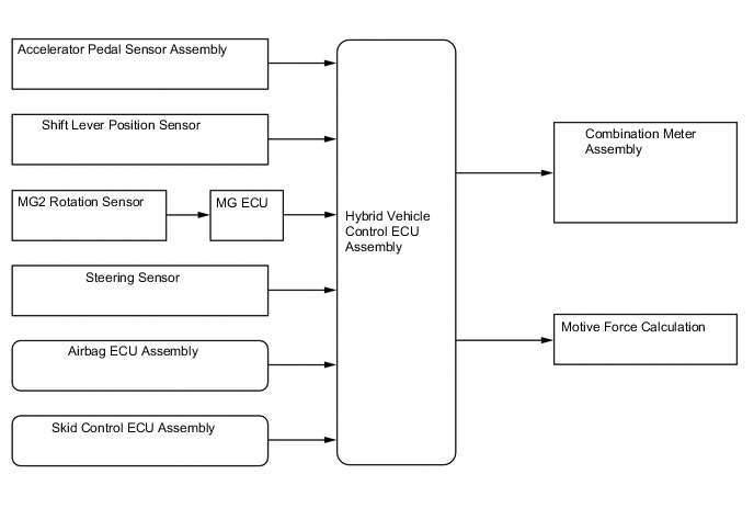
FUNCTION OF MAIN COMPONENTS
Component Function 2GR-FXS Engine The 2GR-FXS engine is a high-expansion ratio Atkinson cycle engine which is compatible with the hybrid system and which generates drive force for driving and energy for electricity generation. P314 Hybrid Transaxle (Hybrid Vehicle Transaxle Assembly) Motor Generator No. 1 (MG1)
-
Driven by the engine and generates high-voltage electricity in order to operate MG2 and MGR*1 and/or to charge the HV battery. Also, MG1 functions as a starter to start the engine.
-
Operated to allow the gear ratio of the power split planetary gear unit to optimally suit the driving conditions of the vehicle.
Motor Generator No. 2 (MG2)
-
Driven by electrical power from MG1 and/or the HV battery, and generates motive force for the front wheels.
-
Generates electricity to recharge the HV battery (regenerative braking) during braking or when the accelerator pedal is not depressed.
Compound Gear Unit Power Split Planetary Gear Distributes the engine motive force as appropriate to directly drive the vehicle as well as MG1. Motor Speed Reduction Planetary Gear Reduces the rotational speed of MG2 in accordance with the characteristics of the planetary gear in order to increase torque. Rotation Sensors (Resolver)
-
MG1 and MG2 are each equipped with a resolver.
-
Sends the rotational speed and direction of the motor to the Motor Generator ECU (MG ECU).
Temperature Sensors
-
MG1 and MG2 are each equipped with a temperature sensor.
-
Measures the temperature of MG1 and MG2.
Q211 Rear Drive Unit (Rear Traction Motor with Transaxle Assembly)*1 Motor Generator Rear (MGR)
-
Driven by electrical power from MG1 and/or the HV battery, it generates motiveforce for the rear wheels.
-
During braking, or when the accelerator pedal is not depressed, it generateselectricity to recharge the HV battery (Regenerative braking).
Rotation Sensor (Resolver)
-
MGR*1 is each equipped with a resolver.
-
Sends the rotational speed and direction of the motor to the Motor Generator ECU (MG ECU).
Temperature Sensor
-
MGR*1 is each equipped with a temperature sensor.
-
Measures the temperature of MGR*1.
Inverter with Converter Assembly Inverter A device that converts high-voltage DC (HV battery) into AC (MG1, MG2 and MGR*1) and vice versa (converts AC into DC). Boost Converter Boosts the voltage of the HV battery from DC 288V to a maximum of DC 650 V and vice versa (drops DC 650 V to DC 288 V). DC-DC Converter Drops the HV battery voltage of DC 288 V into approximately DC 14 V in order to supply electricity to body electrical components, as well as to recharge the auxiliary battery. Motor Generator ECU (MG ECU) Controls the inverter and boost converter in accordance with signals received from the hybrid Vehicle Control ECU assembly, thus operating MG1, MG2, or MGR*1 as either a generator or motor. Temperature Sensors (6) Measure the current of MG1, MG2 and MGR*1. Current Sensors (6) Measure the temperature of the boost converter, IPM for MG1, MG2 and MGR*1, and inverter coolant. HV Battery Assembly HV Battery
-
Supplies electrical power to MG1, MG2 and MGR*1 and the compressor with motor assembly in accordance with the driving conditions of the vehicle.
-
Charged by MG1 and MG2 in accordance with the State Of Charge (SOC) of the HV battery and the driving conditions of the vehicle.
-
Has a nominal (approximate) voltage of DC 288 V (actual voltage will vary depending on various conditions such as temperature, charge or discharge).
Service Plug Grip Shuts off the high-voltage circuit of the HV battery when this plug is removed for vehicle inspection or maintenance. Battery Voltage Sensor
-
Monitors frequency from the battery cooling blower assemblies and conditions of the HV battery such as voltage, temperature and current, and transmits this information to the hybrid vehicle control ECU assembly.
-
Monitors the high voltage system for breakdown of the electrical insulation.
Hybrid Battery Junction Block Assembly System Main Relays Connect and disconnect the high-voltage circuit between the HV battery and the inverter with converter assembly. The hybrid vehicle control ECU assembly controls the SMRs by turning them on or off as appropriate. HV Battery Current Sensor Measures the current of the HV battery. HV Battery Temperature Sensors Detect temperatures in the parts of the HV battery and the intake air temperature from the battery cooling blower assembly. Battery Cooling Blower Assemblies Operate under the control of the hybrid vehicle control ECU assembly in order to cool the HV battery. Auxiliary Battery When the power switch is on (ACC) or on (IG), the auxiliary battery supplies power to the electrical equipment and ECUs. Auxiliary Battery Temperature Sensor (Thermistor Assembly) Measures the temperature of the auxiliary battery to protect the battery. Inverter Radiator Cools the inverter coolant Inverter Water Pump with Motor Assembly Controlled in 4 stages by the hybrid vehicle control ECU assembly in accordance with inverter coolant temperatures in order to cool the inverter coolant. Interlock Switches
-
Inverter Terminal Cover
-
Service Plug Grip
-
Power Cable
Verify that the inverter terminal cover, service plug grip and power cable areinstalled. Power Cable Connects the HV battery to the inverter with converter assembly, the inverter with converter assembly to MG1, MG2 and MGR*1, and the inverter with converter assembly to the compressor with motor assembly. Compressor with Motor Assembly Driven at a speed calculated by the air conditioning amplifier assembly, receives drive requests from the hybrid vehicle control ECU assembly and takes in, compresses and discharges refrigerant. Heater Water Pump (Heater Accessory Assembly) Controlled via the hybrid vehicle control ECU assembly in accordance with signals from the air conditioning amplifier assembly and circulates coolant to ensure heater source stability during idling stop control. Speed Sensors Detect the wheel speed of each of the 4 wheels. Shift Lever Position Sensor Converts the shift lever position into electrical signals and outputs the signals to the hybrid vehicle control ECU assembly. Steering Sensor Detects the direction and angle of the steering wheel. Accelerator Pedal Sensor Assembly Converts the accelerator pedal position into an electrical signal and outputs the signal to the hybrid vehicle control ECU assembly. Brake Pedal Stroke Sensor Assembly Directly detects the extent of the brake pedal stroke operated by the driver. Stop Light Switch Assembly Detects the brake pedal depressing signal. Combination Switch Assembly EV Mode Switch Outputs the EV mode switch signal to the hybrid vehicle control ECU assembly when operated by the driver. Drive Mode Select
-
Outputs the NORMAL or SPORT mode signal to the hybrid vehicle control ECU assembly via the ECM when operated by the driver.
-
Outputs the ECO mode signal to the hybrid vehicle control ECU assembly via the air conditioning amplifier assembly when operated by the driver.
Transmission Control Switch
-
Detects that the shift lever is in S.
-
Detects the shift-up and shift-down operations performed by the driver when the shift lever is in S.
Shift Paddle Switch (Transmission Shift Switch Assembly) Detects the shift-up and shift-down operations performed by the driver. Hybrid Vehicle Control ECU Assembly
-
Performs comprehensive control of the hybrid system. This includes the electric continuously variable transmission and HV battery.
-
Receives information from various sensors as well as from ECUs (ECM, battery voltage sensor, MG ECU and skid control ECU), calculates the required torque and output power based on the information and sends the calculated result to the ECM, MG ECU and skid control ECU assembly.
-
Monitors the SOC of the HV battery.
-
Controls the DC-DC converter assembly.
-
Controls the inverter water pump with motor assembly.
-
Controls the battery cooling blower assemblies.
ECM
-
Controls the engine in accordance with the target engine speed and required engine motive force received from the hybrid vehicle control ECU assembly.
-
Transmits the operating condition signals of the engine to the hybrid vehicle control ECU assembly.
Skid Control ECU
-
Calculates the regenerative braking force that is required and transmits the force to the hybrid vehicle control ECU assembly during braking.
-
Calculates the motive force that is required during the operation of TRC or VSC and transmits the force to the hybrid vehicle control ECU assembly.
Air Conditioning Amplifier Assembly Transmits various air conditioning state signals to the hybrid vehicle control ECU assembly. Airbag ECU Assembly
-
Transmits the airbag deployment signal to the hybrid vehicle control ECU assembly during a collision.
-
Detects the vehicle's longitudinal and lateral acceleration.
-
Detects the vehicle's yaw rate.
Radio Receiver Assembly Displays hybrid system output and charging conditions of the hybrid battery on the energy monitor in the multi-display. Combination Meter Assembly Hybrid System Indicator Indicates the hybrid system output and charging conditions of the hybrid battery to inform the driver. READY Indicator Light Informs the driver that the vehicle is ready to be driven. EV Drive Indicator Light Informs the driver that the EV drive is entered. MIL Turns on when there is a malfunction in the engine control system. Master Warning Light In this context, the primary function of this warning light is to inform the driver of a malfunction in the hybrid system or when the SOC of the HV battery is too low. The light illuminates simultaneously with the sounding of a warning buzzer. Multi-information Display
-
Displays the shift position
-
Displays the shift range.
-
Displays the energy monitor.
-
Displays the EV mode.
-
Displays the drive mode.
-
Displays messages to inform the driver when a malfunction occurs.
-
Shows the system status and appropriate operations to be performed.
-
*: AWD models
-
-
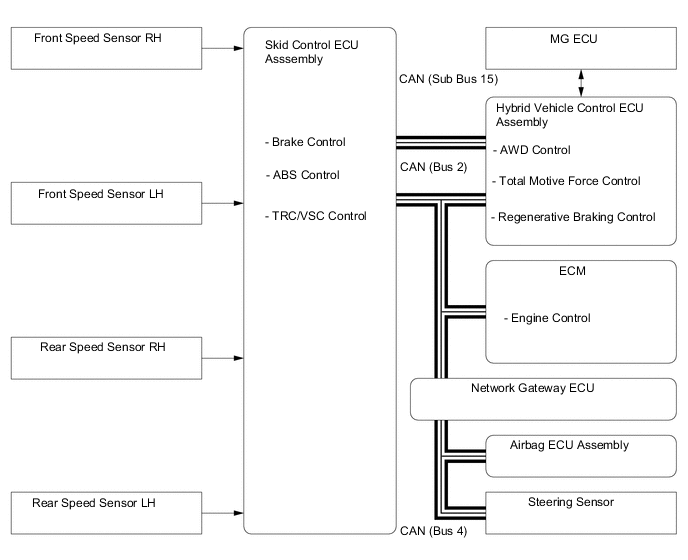
SYSTEM CONTROL
-
Control List
-
The hybrid system consists of the controls listed below.
Control Outline Hybrid Vehicle Control
-
The hybrid vehicle control ECU assembly calculates the target motive force based on the shift lever position sensor, the degree to which the accelerator pedal is depressed, and the vehicle speed. The hybrid vehicle control ECU assembly performs control in order to create the target motive force by optimally combining MG1, MG2, MGR*1 and the engine.
-
The hybrid vehicle control ECU assembly calculates the engine motive force based on the target motive force, which has been calculated based on the requirements of the driver and vehicle conditions. In order to create this motive force, the hybrid vehicle control ECU assembly transmits signals to the ECM.
-
The hybrid vehicle control ECU assembly monitors the conditions of the HV battery and battery cooling blower assemblies to perform control using feedback to keep the HV battery at a predetermined temperature.
System Monitoring Control The hybrid vehicle control ECU assembly monitors the State Of Charge (SOC) of the HV battery and the temperature of the HV battery, MG1, MG2 and MGR*1, in order to optimally control these items. Shut Down Control When the shift lever is in N, the hybrid vehicle control ECU assembly performs shut down control to stop driving MG1, MG2 and MGR*1. System Main Relay (SMR) Control To ensure that it is possible to connect and disconnect the high voltage circuits reliably, the hybrid vehicle control ECU assembly controls the 3 System Main Relays (SMRs) to connect and disconnect the high voltage circuits from the HV battery. The hybrid vehicle control ECU assembly also uses the timing of the operation of the SMRs to monitor the operation of the relay contacts. State Of Charge (SOC) Control
-
The hybrid vehicle control ECU assembly calculates the SOC by estimating the charging and discharging amperage of the HV battery.
-
The hybrid vehicle control ECU assembly constantly performs charge/discharge control based on the calculated SOC in order to maintain the SOC within its target range.
Inverter Coolant Cooling Control In order to cool the inverter with converter assembly, MG1 and MG2, the hybrid vehicle control ECU assembly regulates the inverter water pump with motor assembly in accordance with the signals from the temperature sensor for the inverter coolant. HV Battery Cooling Control In order to maintain the HV battery temperature at the optimal level, the hybrid vehicle control ECU assembly regulates the battery cooling blower assemblies in accordance with the signals from the HV battery temperature sensor. Auxiliary Battery Charging Control The hybrid vehicle control ECU assembly uses the auxiliary battery temperature sensor (thermistor assembly) to monitor the temperature of the auxiliary battery. The hybrid vehicle control ECU assembly performs charge control based on the temperature information from the auxiliary battery. ECM Control The ECM receives the target engine speed and required engine motive force sent from the hybrid vehicle control ECU assembly, and controls the Electronic Throttle Control System-intelligent (ETCS-i), fuel injection volume, ignition timing and Variable Valve Timing-intelligent (VVT-i) system. Motor Generator Main Control
-
MG1, which is driven by the engine, generates high voltage (alternating current) in order to operate MG2 and MGR*1, and charge the HV battery via the inverter. Also, MG1 functions as a starter to start the engine.
-
MG2, which is driven by electrical power from MG1 and/or the HV battery, generates motive force for the front wheels.
-
MGR, which is driven by the electrical power from MG1 and/or the HV battery, generates motive force for the rear wheels.*1
-
MG2 generates electricity to charge the HV battery (regenerative braking control) during braking or when the accelerator pedal is not being depressed.
-
Rotation sensors detect the speed and the position of MG1, MG2 and MGR*1 for use by the hybrid vehicle control ECU. Rotation sensor signals are transmitted to the hybrid vehicle control ECU assembly via the Motor Generator ECU (MG ECU).
-
Temperature sensors mounted in MG1, MG2 and MGR*1 detect the temperature for use by the hybrid vehicle control ECU assembly.
Boost Converter Control
-
The boost converter boosts the HV battery voltage from a nominal voltage of DC 288 V to a maximum voltage of DC 650 V, in accordance with the signals provided by the hybrid vehicle control ECU assembly via the MG ECU.
-
The inverter converts the alternating current generated by MG1 or MG2 into a direct current. The boost converter reduces the generated voltage from up to 650 V to approximately DC 288 V for the HV battery in accordance with the signals provided by the hybrid vehicle control ECU assembly via the MG ECU.
Inverter Control
-
The inverter converts direct current from the HV battery into an alternating current for MG1, MG2 and MGR*1, or vice versa, in accordance with the signals provided by the hybrid vehicle control ECU assembly via the MG ECU. In addition, the inverter is used to transfer power from MG1 to MG2.
-
Via the MG ECU, the hybrid vehicle control ECU assembly sends signals to the power transistors on the Intelligent Power Modules (IPMs) in the inverter for switching the U, V and W phases of MG1, MG2 and MGR*1, in order to drive MG1, MG2 and MGR*1.
-
The hybrid vehicle control ECU assembly shuts down the inverter when the ECU receives an overheat, overcurrent or fault voltage signal from the inverter via the MG ECU.
Hybrid Vehicle Converter Assembly Control
-
Reduces the voltage from DC 288 V (nominal) to DC 14 V (nominal) in order to supply electricity to body electrical components, as well as to recharge the auxiliary battery (DC 12 V).
-
This converter keeps the auxiliary battery at a constant voltage.
E-Four System Control*1 E-Four system control calculates the torque distribution ratio of front and rear wheels based on various signals from each sensor sent by the hybrid vehicle control ECU assembly using its built-in AWD control. Battery Voltage Sensor Control The battery voltage sensor monitors the insulation of the high voltage electrical system for leakage. In addition, the sensor converts the feedback signals of the battery cooling blower assemblies and the conditions of the HV battery (which are needed by the hybrid vehicle control ECU assembly to perform SOC control and HV battery cooling control) into digital signals, and transmits the signals to the hybrid vehicle control ECU assembly. Shift Control The hybrid vehicle control ECU assembly the shift position (P, R, N, D or S) in accordance with the signals provided by the shift lever position sensor and the transmission control switch, and controls MG1, MG2, MGR*1 and the engine to match the selected shift position. Skid Control ECU Control Regenerative Braking Cooperative Control During braking, the skid control ECU assembly calculates the required regenerative braking force and transmits a signal to the hybrid vehicle control ECU assembly. Upon receiving this signal, the hybrid vehicle control ECU assembly transmits an actual regenerative braking control value to the skid control ECU assembly. Based on this result, the skid control ECU assembly calculates and executes the required hydraulic pressure braking force. TRC/VSC Cooperative Control The skid control ECU assembly transmits a request to the hybrid vehicle control ECU assembly to limit motive force while the TRC or VSC is operating. The hybrid vehicle control ECU assembly controls the engine, MG1, MG2 and MGR*1 in accordance with the present driving conditions in order to suppress the motive force. During Collision Control During a collision, if the hybrid vehicle control ECU assembly receives an airbag deployment signal from the airbag ECU assembly, the ECU turns the SMRs off in order to shut off the high voltage power supplied to the hybrid system by the HV battery. EV Mode Control When the EV mode switch is manually operated by the driver, the hybrid vehicle control ECU assembly operates to run the vehicle using only MG2 if the required conditions are satisfied. Drive Mode Select Control Optimally controls the outputs of MG1, MG2 and MGR*1 and the engine in accordance with the following drive modes: NORMAL, ECO, SPORT*2 and SPORT S/S+*3 modes. Brake Override System The driving torque is restricted when both the accelerator and brake pedals are depressed. (For the Activation Conditions and Inspection Method, refer to the Repair Manual.) Drive Start Control System Even if the driver is in a hurry and abnormal accelerator pedal and shift operations are performed, vehicle speed and acceleration are restricted to improve the sense of security felt by the driver.
-
*1: AWD models
-
*2: Models without AVS
-
*3: Models with AVS
-
-
-
Hybrid System Activation (READY-on State)
-
The hybrid system is activated by pressing the power switch while the brake pedal is being depressed. At this time, the READY indicator light flashes until the system check is completed. When the READY indicator light turns on, the hybrid system has started and the vehicle is ready to drive.
-
Even if the driver turns the power switch on (READY), sometimes the hybrid vehicle control ECU assembly will not start the engine. The engine will only start if conditions such as engine coolant temperature, SOC, HV battery temperature and electrical load require an engine start.
-
After driving, when the driver stops the vehicle and moves the shift lever to P, the hybrid vehicle control ECU assembly allows the engine to continue running. The engine will stop after the SOC, HV battery temperature and electrical load reach a specified level.
Note
When the hybrid system is unavoidably required to be stopped while driving, the system can be forced to stop by pressing and holding the power switch for approximately 2 seconds or more or pushing the power switch 3 times or more in a row. At this time, the power source will change to on (ACC). The reafter, the hybrid system can be restarted by pressing the power switch with the shift lever in N (the system may not restart due to the vehicle conditions).
-
-
EV Drive Mode
-
When all required conditions, some of which are listed below, are satisfied, EV drive mode can be used.
Operating Condition
-
The hybrid system temperature is not high. (The hybrid system temperature will be high when the outside air temperature is high or after the vehicle has traveled up a hill or at high speeds.)
-
The hybrid system temperature is not low. (The hybrid system temperature will be low after the vehicle has been left for a long time when the outside air temperature is low.)
-
The SOC is approximately 50% or higher.
-
The vehicle speed is approximately 50 km/h (25 mph) or less. (Engine coolant temperature: 70°C (158°F) ormore)
-
The accelerator pedal depression amount is a certain level or below.
-
The defroster is off.
-
The cruise control system is not operating.
-
-
-
Drive Mode Select Control
-
The drive mode can be selected by operating the drive mode select.
-
The selected drive mode will be shown on the multi-information display in the combination meter assembly.
-
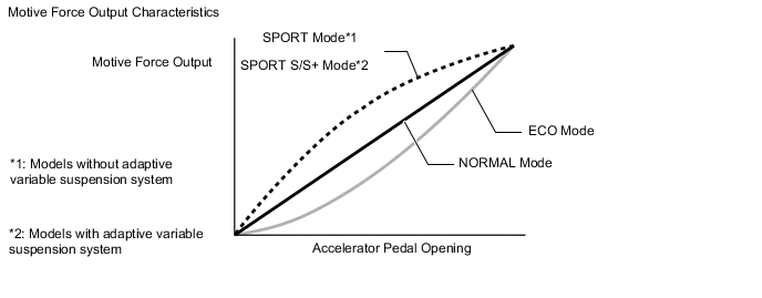
The drive characteristics of each drive mode are as follows:
Drive Mode Outline NORMAL Mode This drive mode provides optimum driveability. ECO Mode The hybrid vehicle control ECU assembly optimizes fuel economy and driving performance by gently generating the motive force in comparison to the accelerator pedal operation. At the same time, the ECU supports eco driving by optimizing the air conditioning performance. SPORT Mode*1
SPORT S Mode*2
The hybrid vehicle control ECU assembly controls motive force in the intermediate area of accelerator pedal opening to a greater degree than that of NORMAL mode, thus improving acceleration performance. In addition, engine speed response performance has been improved in the high area of accelerator pedal opening, thus producing a sporty drive. SPORT S+ Mode*2 In addition to the control when in SPORT S mode, the suspension control system and steering control system have been integrated to shift to SPORT S+ mode, improved operability and stability have been aimed for even without losing comfort and a control which enables operation appropriate to the driver's intention is performed. *1: Models without adaptive variable suspension system
*2: Models with adaptive variable suspension system
-
-
Drive Start Control System
-
When abnormal driver accelerator pedal and shift operations are detected, the system limits the motive force and informs the driver.
CAUTION:
When the system is operating, even if the driver depresses and holds the accelerator pedal, motive force may increase on an uphill slope and decrease on a downhill slope. This behavior allows the system to restrict the vehicle speed and acceleration below the predetermined limit on slopes and is not a malfunction.
-
Control during Reverse Operation
-
Responds to excessive depression of the accelerator pedal while operating in reverse.
-
Corrects motive force according to the road grade and steering angle.
Control Start Conditions (When all of the following conditions are met, control starts.)
-
Shift position is P.
-
Accelerator pedal is depressed.
Control Operation Limits the motive force so the vehicle speed and acceleration are at or below a certain level. Control Stop Conditions
-
Shift position is not R.
-
Accelerator pedal is fully released.
-
-
-
Control during Manual Shift Operation
-
Responds to shift operations with the accelerator pedal depressed.
-
Changes the limit amount according to the manual shift operation pattern.
-
Corrects motive force according to the road grade and steering angle.
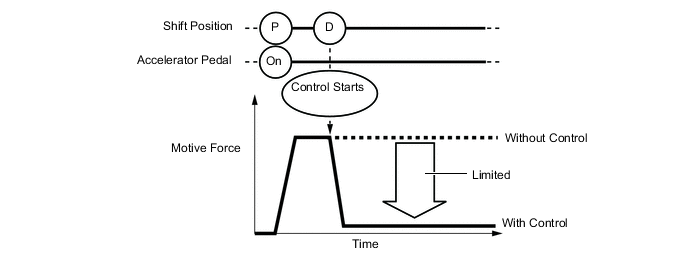
Control when Starting Off from a Parked Position Control Start Conditions (When all of the following conditions are met, control starts.)
-
Shift position is changed from P to D, or P to R.
-
Accelerator opening angle is approximately 1/5 or higher.
Control Operation Limits the motive force so the vehicle speed and acceleration are at or below a certain level. Control Stop Conditions
-
Shift position is P or N.
-
Accelerator pedal is fully released.
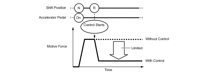
Figure 1. Image of Control when Starting Off from a Parked Position
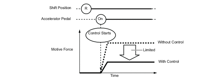
Control during Other Situations Control Start Conditions (When all of the following conditions are met, control starts.)
-
Shift position is changed from R to D, D to R, or N to R.
-
Accelerator opening angle is approximately 1/5 or higher.
Control Operation Limits the motive force so the vehicle speed and acceleration are at or below a certain level. Control Stop Conditions
-
Shift position is P or N.
-
Accelerator pedal is fully released.
Figure 2. Image of Control during Other Situations
CAUTION:
-
The motive force restraint level differs in the above 2 situations.
-
During control while a manual shift operation is performed (from control start until the accelerator pedal is released), the system informs the driver of the control via the multi-information display.
-
-
-
-
E-Four System Control (AWD Models)
-
Based on information provided by various sensors, the AWD ECU assembly built into the hybrid vehicle control ECU assembly calculates the optimum voltage and current required to distribute the appropriate amount of drive torque to the rear wheels, and controls MG2 and MGR accordingly.
E-Four System Control Start Off Control Drives the rear wheels during starting off to ensure a smooth start-off. Normal Control Optimally controls the drive force of the rear wheels to ensure acceleration performance. Cornering Control Optimally controls the drive force of the rear wheels based on yawrate feedback control and the drivers input in order to improve vehicle stability.
-
Start Off Control
-
The system optimally controls the drive force of the rear wheels to ensure start-off performance.
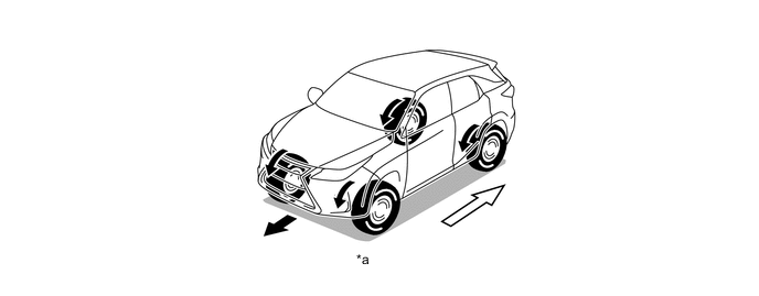
*a Straightline Driving - - 
Torque Distribution to Rear Wheels - - -
-
Normal Control
-
The system optimizes the drive force of the rear wheels to ensure excellent acceleration performance based on various signals such as the throttle opening angle, engine speed, shift position, etc.
-
When the system judges that the vehicle is traveling steadily based on the throttle opening signal, the driving condition of the vehicle, etc., it reduces the drive force of the rear wheels. This allows the vehicle to operate similar to a front-wheel-drive vehicle, improving fuel economy.
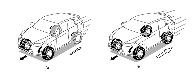
*a Steady Driving *b Straightline Acceleration Torque Distribution to Rear Wheels - - -
-
Cornering Control
-
The desired driving path of the driver is estimated using information such as the vehicle speed, steering angle, etc., to change drive force distribution according to driving conditions. As a result, excellent driving stability is ensured.
-
Pre-torque control, which is based on driver operation input, and yawrate feedback control, which is based on the vehicle status, are used to correct vehicle oversteer and understeer and achieve the tracing performance desired by the driver.
-
Pre-torque control is linked with driver steering wheel operations and distributes drive force to the rear wheels to improve steering performance when entering a corner (front and rear drive force distribution is 90:10).
-
Yawrate feedback control performs high-speed computation of the ideal yaw rate (calculated by the 4WD ECU assembly when the vehicle is in motion) and actual yaw rate, detects vehicle steering characteristics (oversteer or understeer), and performs optimal control to distribute drive force to the front or rear wheels if required for correction (front and rear drive force distribution changes from 90:10 to 50:50).
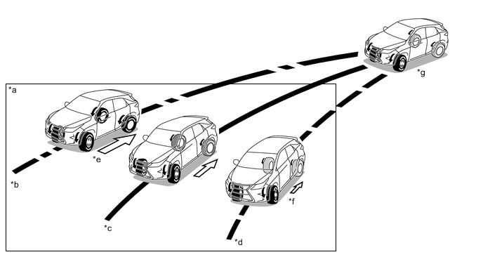
*a Yawrate Feedback Control *b Understeer Tendency *c Target Line *d Oversteer Tendency *e Drive Force Distribution to Rear Wheels Increased *f Drive Force Distribution to Rear Wheels Reduced *g Pre-torque Control - - -
-
AWD Operation Condition Display
-
The operation conditions of the AWD system, which automatically operates according to the longitudinal and lateral g-force and steering angle while the vehicle is being driven, are displayed on the multi-information display.
-
With this display, even on a slippery road, the user can monitor the condition of the AWD control system as it operates in accordance with the surrounding conditions. This contributes to an improved feeling of safety provided by AWD system.
-
AWD operation condition display mode can be enabled or disabled by operating the steering pad switch assembly.
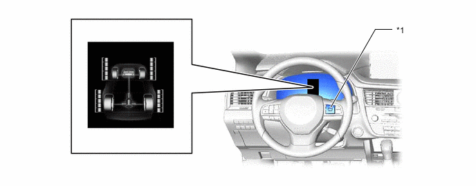
*1 Steering Pad Switch Assembly - -
-
-
Failsafe
-
When there is a possibility of causing damage to the drive train due to rough driving or a malfunction in the AWD system, the system illuminates or blinks the master warning light and displays the message on the multi-information display to inform the driver and stops AWD control to operate the vehicle in front-wheel-drive.
-
When the master warning light illuminates or blinks as a message is displayed on the multi-information display, perform either of the following procedures. Reduce the speed of the vehicle until the master warning light turns off. Stop the vehicle and idle the engine until the master warning light turns off.
-
When a stable system condition is determined, AWD control automatically resumes.
Vehicle Condition Control Combination Meter Assembly Master Warning Light Multi-information Display AWD system malfunction 2WD driving
(control prohibited)
Illuminates AWD System
Malfunction
2WD Mode
Engaged
Visit Your Dealer
AWD excess driving 2WD driving
(control prohibited)
Illuminates HYBRID System
Overheated
2WD Mode
Engaged
-
-
-
-
DIAGNOSIS
-
A diagnosis function is provided in consideration of serviceability in order to simplify the inspection of systems. . For details of the diagnosis function, refer to Repair Manual.
-