ENGINE COMPARTMENT THREE-DIMENSIONAL DISTANCE
Point E, e, H, h on the vehicle are asymmetrical.
In cases in which only one dimension is given, left and right are symmetrical.
For symbols, capital letters indicate right side of vehicle, small letters indicate left side of vehicle (seen from rear).
Symbol |
Name |
Hole Diameter mm (in.) |
|---|---|---|
A, a |
Front Fender Installation Nut |
M6 (0.24) |
B, b |
Front Spring Support Plate Standard Hole |
φ10 (0.39) |
C, c |
Hood Hinge Installation Nut |
M8 (0.31) |
D |
Cowl Top Inner Panel Center Mark |
- |
E, e |
Engine Mounting Installation Nut |
M10 (0.39) |
F, f |
Front Side Member Standard Hole |
φ10 (0.39) |
G, g |
Radiator Upper Support Standard Hole |
φ15 (0.59) |
H, h |
Bumper Support Installation Hole |
φ9 (0.35) |
J, j |
Front Bumper Reinforcement Installation Nut |
M10 (0.39) |
K, k |
Front Bumper Reinforcement Installation Nut |
M10 (0.39) |
L, l |
Front Crossmember Side Gusset Standard Hole |
φ10 (0.39) |
M, m |
Front Fender Mounting Bracket Standard Hole |
φ10 (0.39) |
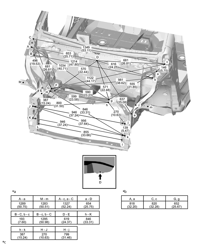
*a |
Distance between points other than those above |
*b |
Height from Imaginary Datum Line |
*c |
mm (in.) |
- |
- |