LIGHTING SYSTEM Ambient Illumination Light Circuit
DESCRIPTION
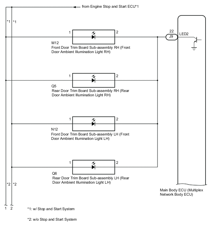
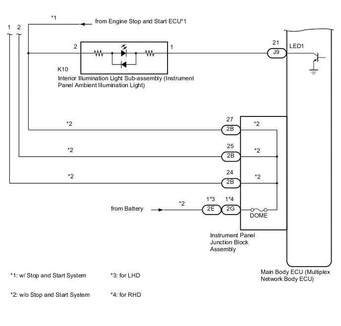
The main body ECU (multiplex network body ECU) controls the ambient illumination lights.
WIRING DIAGRAM
CAUTION / NOTICE / HINT
Note
-
Inspect the lights for circuits related to this system before performing the following procedure.
-
Before replacing the main ECU (multiplex network body ECU), refer to Service Bulletin.
-
The vehicle battery supplies power to the main body ECU (multiplex network body ECU) via the door control battery. Therefore, before proceeding with troubleshooting, perform an on-vehicle inspection and confirm that the main body ECU (multiplex network body ECU) power source circuit is normal.*
-
*: w/o Canister Pump Module with Door Ajar Warning Buzzer Function
PROCEDURE
-
PERFORM ACTIVE TEST USING GTS
-
Connect the GTS to the DLC3.
-
Turn the engine switch on (IG).
-
Turn the GTS on.
-
Enter the following menus: Body Electrical / Main Body / Active Test.
-
Perform the Active Test according to the display on the GTS.
Body Electrical > Main Body > Active TestTester Display Measurement Item Control Range Diagnostic Note Interior Illumination Light1 Instrument panel ambient illumination light ON or OFF Preconditions for using the Active Test to check dimmer controlled illumination:
-
Engine switch on.
-
Shift lever is in any position other than P.
Interior Illumination Light2 Door ambient illumination light ON or OFF Preconditions for using the Active Test to check dimmer controlled illumination:
-
Engine switch on.
-
Shift lever is in any position other than P.
Body Electrical > Main Body > Active TestTester Display Interior Illumination Light1
Body Electrical > Main Body > Active TestTester Display Interior Illumination Light2 OK Ambient illumination lights comes on. Result Result Proceed to OK A NG (All ambient lights do not illuminate) (w/o Stop and start system) B NG (Instrument panel ambient illumination light does not illuminate) (w/o Stop and start system) C NG (Door ambient illumination light does not illuminate) (w/o Stop and start system) D NG (Instrument panel ambient illumination light does not illuminate) (w/ Stop and start system) E NG (Door ambient illumination light does not illuminate) (w/ Stop and start system) F -
A 
PROCEED TO NEXT SUSPECTED AREA SHOWN IN PROBLEM SYMPTOMS TABLE Click here
C 
INSPECT INSTRUMENT PANEL JUNCTION BLOCK ASSEMBLY Click here
D
INSPECT INSTRUMENT PANEL JUNCTION BLOCK ASSEMBLY Click here
E
CHECK HARNESS AND CONNECTOR (ENGINE STOP AND START ECU - INTERIOR ILLUMINATION LIGHT SUB-ASSEMBLY) Click here
F
CHECK HARNESS AND CONNECTOR (ENGINE STOP AND START ECU - DOOR TRIM BOARD SUB-ASSEMBLY) Click here
B 
-
-
CHECK HARNESS AND CONNECTOR (POWER SOURCE - INSTRUMENT PANEL JUNCTION BLOCK ASSEMBLY)
-
Disconnect the 2E*1 or 2G*2 instrument panel junction block assembly connector.
-
Measure the voltage according to the value(s) in the table below.
Standard Voltage Tester Connection Condition Specified Condition 2E-1 - Body ground*1 Always 11 to 14 V 2G-1 - Body ground*2 Always 11 to 14 V
-
*1: for LHD
-
*2: for RHD
Result Proceed to OK NG -
NG
REPAIR OR REPLACE HARNESS OR CONNECTOR
OK
-
-
INSPECT INSTRUMENT PANEL JUNCTION BLOCK ASSEMBLY
-
Disconnect the 2B instrument panel junction block assembly connector.
-
Measure the resistance according to the value(s) in the table below.
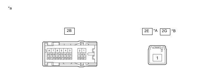
*A for LHD *B for RHD *a Component without harness connected
(Instrument Panel Junction Block Assembly)
- - Standard Resistance for LHD Tester Connection Condition Specified Condition 2E-1 - 2B-24 Always Below 1 Ω 2E-1 - 2B-25 Always Below 1 Ω 2E-1 - 2B-27 Always Below 1 Ω for RHD Tester Connection Condition Specified Condition 2G-1 - 2B-24 Always Below 1 Ω 2G-1 - 2B-25 Always Below 1 Ω 2G-1 - 2B-27 Always Below 1 Ω Result Proceed to OK NG
OK
PROCEED TO NEXT SUSPECTED AREA SHOWN IN PROBLEM SYMPTOMS TABLE Click here
NG
REPLACE INSTRUMENT PANEL JUNCTION BLOCK ASSEMBLY Click here
-
-
INSPECT INSTRUMENT PANEL JUNCTION BLOCK ASSEMBLY
-
Disconnect the 2B instrument panel junction block assembly connector.
-
Disconnect the 2E*1 or 2G*2 instrument panel junction block assembly connector.
-
Measure the resistance according to the value(s) in the table below.
*A for LHD *B for RHD *a Component without harness connected
(Instrument Panel Junction Block Assembly)
- - Standard Resistance for LHD Tester Connection Condition Specified Condition 2E-1 - 2B-27 Always Below 1 Ω Standard Resistance for RHD Tester Connection Condition Specified Condition 2G-1 - 2B-27 Always Below 1 Ω
-
*1: for LHD
-
*2: for RHD
Result Proceed to OK NG -
NG
REPLACE INSTRUMENT PANEL JUNCTION BLOCK ASSEMBLY Click here
OK
-
-
CHECK HARNESS AND CONNECTOR (INTERIOR ILLUMINATION LIGHT SUB-ASSEMBLY - INSTRUMENT PANEL JUNCTION BLOCK ASSEMBLY)
-
Disconnect the K10 interior illumination light sub-assembly connector.
-
Measure the resistance according to the value(s) in the table below.
Standard Resistance Tester Connection Condition Specified Condition K10-2 - 2B-27 Always Below 1 Ω K10-2 or 2B-27 - Body ground Always 10 kΩ or higher Result Proceed to OK NG
NG
REPAIR OR REPLACE HARNESS OR CONNECTOR
OK
-
-
CHECK HARNESS AND CONNECTOR (INTERIOR ILLUMINATION LIGHT SUB-ASSEMBLY - MAIN BODY ECU (MULTIPLEX NETWORK BODY ECU))
-
Disconnect the J9 main body ECU (multiplex network body ECU) connector.
-
Measure the resistance according to the value(s) in the table below.
Standard Resistance Tester Connection Condition Specified Condition K10-1 - J9-21 (LED1) Always Below 1 Ω K10-1 or J9-21 (LED1) - Body ground Always 10 kΩ or higher Result Proceed to OK NG
OK
REPLACE MAIN BODY ECU (MULTIPLEX NETWORK BODY ECU) Click here
NG
REPAIR OR REPLACE HARNESS OR CONNECTOR
-
-
INSPECT INSTRUMENT PANEL JUNCTION BLOCK ASSEMBLY
-
Disconnect the 2B instrument panel junction block assembly connector.
-
Disconnect the 2E*1 or 2G*2 instrument panel junction block assembly connector.
-
Measure the resistance according to the value(s) in the table below.
*A for LHD *B for RHD *a Component without harness connected
(Instrument Panel Junction Block Assembly)
- - Standard Resistance for LHD Tester Connection Condition Specified Condition 2E-1 - 2B-24 Always Below 1 Ω 2E-1 - 2B-25 Always Below 1 Ω Standard Resistance for RHD Tester Connection Condition Specified Condition 2G-1 - 2B-24 Always Below 1 Ω 2G-1 - 2B-25 Always Below 1 Ω
-
*1: for LHD
-
*2: for RHD
Result Proceed to OK NG -
NG
REPLACE INSTRUMENT PANEL JUNCTION BLOCK ASSEMBLY Click here
OK
-
-
CHECK HARNESS AND CONNECTOR (DOOR TRIM BOARD SUB-ASSEMBLY - INSTRUMENT PANEL JUNCTION BLOCK ASSEMBLY)
-
Disconnect the M12 front door trim board sub-assembly RH connector.
-
Disconnect the N12 front door trim board sub-assembly LH connector.
-
Disconnect the Q5 rear door trim board sub-assembly RH connector.
-
Disconnect the Q6 rear door trim board sub-assembly LH connector.
-
Measure the resistance according to the value(s) in the table below.
Standard Resistance Tester Connection Condition Specified Condition M12-1 - 2B-24 Always Below 1 Ω M12-1 or 2B-24 - Body ground Always 10 kΩ or higher Q5-1 - 2B-24 Always Below 1 Ω Q5-1 or 2B-24 - Body ground Always 10 kΩ or higher N12-1 - 2B-25 Always Below 1 Ω N12-1 or 2B-25 - Body ground Always 10 kΩ or higher Q6-1 - 2B-25 Always Below 1 Ω Q6-1 or 2B-25 - Body ground Always 10 kΩ or higher Result Proceed to OK NG
NG
REPAIR OR REPLACE HARNESS OR CONNECTOR
OK
-
-
CHECK HARNESS AND CONNECTOR (DOOR TRIM BOARD SUB-ASSEMBLY - MAIN BODY ECU (MULTIPLEX NETWORK BODY ECU))
-
Disconnect the J9 main body ECU (multiplex network body ECU) connector.
-
Measure the resistance according to the value(s) in the table below.
Standard Resistance Tester Connection Condition Specified Condition M12-2 - J9-22 (LED2) Always Below 1 Ω M12-2 or J9-22 (LED2) - Body ground Always 10 kΩ or higher Q5-2 - J9-22 (LED2) Always Below 1 Ω Q5-2 or J9-22 (LED2) - Body ground Always 10 kΩ or higher N12-2 - J9-22 (LED2) Always Below 1 Ω N12-2 or J9-22 (LED2) - Body ground Always 10 kΩ or higher Q6-2 - J9-22 (LED2) Always Below 1 Ω Q6-2 or J9-22 (LED2) - Body ground Always 10 kΩ or higher Result Proceed to OK NG
OK
REPLACE MAIN BODY ECU (MULTIPLEX NETWORK BODY ECU) Click here
NG
REPAIR OR REPLACE HARNESS OR CONNECTOR
-
-
CHECK HARNESS AND CONNECTOR (ENGINE STOP AND START ECU - INTERIOR ILLUMINATION LIGHT SUB-ASSEMBLY)
-
Disconnect the K10 interior illumination light sub-assembly connector.
-
Measure the voltage according to the value(s) in the table below.
Standard Voltage Tester Connection Condition Specified Condition K10-2 - Body ground Always 10.5 to 16 V Result Proceed to OK NG
NG
GO TO STOP AND START SYSTEM Click here
OK
-
-
CHECK HARNESS AND CONNECTOR (INTERIOR ILLUMINATION LIGHT SUB-ASSEMBLY - MAIN BODY ECU (MULTIPLEX NETWORK BODY ECU))
-
Disconnect the J9 main body ECU (multiplex network body ECU) connector.
-
Measure the resistance according to the value(s) in the table below.
Standard Resistance Tester Connection Condition Specified Condition K10-1 - J9-21 (LED1) Always Below 1 Ω K10-1 or J9-21 (LED1) - Body ground Always 10 kΩ or higher Result Proceed to OK NG
OK
REPLACE MAIN BODY ECU (MULTIPLEX NETWORK BODY ECU) Click here
NG
REPAIR OR REPLACE HARNESS OR CONNECTOR
-
-
CHECK HARNESS AND CONNECTOR (ENGINE STOP AND START ECU - DOOR TRIM BOARD SUB-ASSEMBLY)
-
Disconnect the M12 front door trim board sub-assembly RH connector.
-
Disconnect the N12 front door trim board sub-assembly LH connector.
-
Disconnect the Q5 rear door trim board sub-assembly RH connector.
-
Disconnect the Q6 rear door trim board sub-assembly LH connector.
-
Measure the voltage according to the value(s) in the table below.
Standard Voltage Tester Connection Condition Specified Condition M12-1 - Body ground Always 10.5 to 16 V N12-1 - Body ground Always 10.5 to 16 V Q5-1 - Body ground Always 10.5 to 16 V Q6-1 - Body ground Always 10.5 to 16 V Result Proceed to OK NG
OK
GO TO STEP 9 Click here
NG
GO TO STOP AND START SYSTEM Click here
-