LIGHTING SYSTEM ACC Signal Circuit
| DTC Code | DTC Name |
|---|---|
| ACC Signal Circuit |
DESCRIPTION
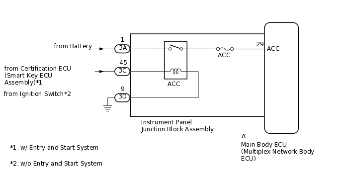
This circuit detects whether the ignition switch is ACC or off, and sends this information to the main body ECU (multiplex network body ECU).
WIRING DIAGRAM
CAUTION / NOTICE / HINT
Inspect the fuses for circuits related to this system before performing the following inspection procedure.
When replacing the main body ECU (multiplex network body ECU), make sure to replace it with a new one.
PROCEDURE
READ VALUE USING GTS (ACC SW)
Using the GTS, read the Data List.
Body Electrical > Main Body > Data List
Tester Display
Measurement Item
Range
Normal Condition
Diagnostic Note
ACC SW
Ignition switch ACC signal
ON or OFF
ON: Ignition switch ACC
OFF: Ignition switch off
"ON" is also displayed for this item when the ignition switch is ON.
Body Electrical > Main Body > Data List
Tester Display
ACC SW
OK
The display is as specified in the normal condition column.
Result
Proceed to
OK
NG
CHECK HARNESS AND CONNECTOR (INSTRUMENT PANEL JUNCTION BLOCK ASSEMBLY - BATTERY AND BODY GROUND)
-
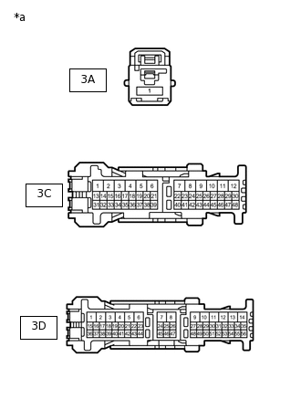
*a
Front view of wire harness connector
(to Instrument Panel Junction Block Assembly)
Disconnect the instrument panel junction block assembly connectors.
Measure the voltage according to the value(s) in the table below.
Standard Voltage
Tester Connection
Condition
Specified Condition
3A-1 - Body ground
Always
11 to 14 V
3C-45 - Body ground
Ignition switch ACC
11 to 14 V
Measure the resistance according to the value(s) in the table below.
Standard Resistance
Tester Connection
Condition
Specified Condition
3D-9 - Body ground
Always
Below 1 Ω
Result
Proceed to
OK
NG
NG REPAIR OR REPLACE HARNESS OR CONNECTOR
-
CHECK INSTRUMENT PANEL JUNCTION BLOCK ASSEMBLY (ACC RELAY)
-
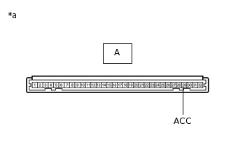
*a
Component without harness connected
(Instrument Panel Junction Block Assembly)
Remove the instrument panel junction block assembly connectors.
for LHD:
for RHD:
Reconnect the 3A, 3C and 3D instrument panel junction block assembly connectors.
Measure the voltage according to the value(s) in the table below.
Standard Voltage
Tester Connection
Switch Condition
Specified Condition
A-29 (ACC) - Body ground
Ignition switch ACC
11 to 14 V
Result
Proceed to
OK
NG
-