LIGHTING SYSTEM Headlight Signal Circuit
DESCRIPTION
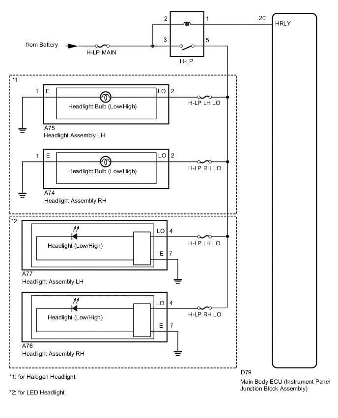
Illumination of the low beam headlight is controlled by the main body ECU (instrument panel junction block assembly).
WIRING DIAGRAM
CAUTION / NOTICE / HINT
Note
-
Recognition code registration is necessary when replacing the main body ECU (instrument panel junction block assembly).
-
If the main body ECU (instrument panel junction block assembly) is replaced, refer to the Service Bulletin.
-
As the door control battery is installed between the vehicle battery and main body ECU (instrument panel junction block assembly), first perform the inspections in On-Vehicle Inspection to confirm that there are no malfunctions in the power source circuit for the main body ECU (instrument panel junction block assembly) before performing this troubleshooting procedure.
Tech Tips
Inspect the fuses for circuits related to this system before performing the following inspection procedure.
PROCEDURE
-
PERFORM ACTIVE TEST USING GTS (HEADLIGHT RELAY)
-
Connect the GTS to the DLC3.
-
Turn the ignition switch to ON.
-
Turn the GTS on.
-
Enter the following menus: Body Electrical / Main Body / Active Test / Headlight Relay.
-
Check that the headlights (low) turn on/off.
Main Body Tester Display Test Part Control Range Diagnostic Note Headlight Relay Headlight ON/OFF - OK Headlights (low) turn on/off.
OK 
PROCEED TO NEXT SUSPECTED AREA SHOWN IN PROBLEM SYMPTOMS TABLE Click here
NG 
-
-
INSPECT H-LP RELAY
-
Remove the H-LP relay from the engine room No. 1 relay block.
-
Inspect the H-LP relay Click here.
NG
REPLACE H-LP RELAY
OK
-
-
CHECK HARNESS AND CONNECTOR (H-LP RELAY - BATTERY)
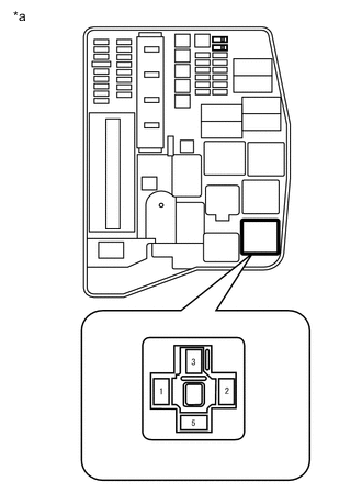
Text in Illustration *a Front view of wire harness connector
(to H-LP Relay)
-
Remove the H-LP relay from the engine room No. 1 relay block.
-
Measure the voltage according to the value(s) in the table below.
Standard Voltage Tester Connection Condition Specified Condition H-LP relay terminal 2 - Body ground Always 11 to 14 V H-LP relay terminal 3 - Body ground Always 11 to 14 V
NG
REPAIR OR REPLACE HARNESS OR CONNECTOR
OK
-
-
CHECK HARNESS AND CONNECTOR (H-LP RELAY - MAIN BODY ECU [INSTRUMENT PANEL JUNCTION BLOCK ASSEMBLY])
-
Remove the H-LP relay from the engine room No. 1 relay block.
-
Disconnect the D79 main body ECU (instrument panel junction block assembly) connector.
-
Measure the resistance according to the value(s) in the table below.
Standard Resistance Tester Connection Condition Specified Condition H-LP relay terminal 1 - D79-20 (HRLY) Always Below 1 Ω H-LP relay terminal 1 - Body ground Always 10 kΩ or higher
NG
REPAIR OR REPLACE HARNESS OR CONNECTOR
OK
-
-
CHECK HARNESS AND CONNECTOR (H-LP RELAY - HEADLIGHT ASSEMBLY LH)
-
Remove the H-LP relay from the engine room No. 1 relay block.
-
Disconnect the A75*1 or A77*2 front fog light assembly LH connector.
-
*1: for Halogen Headlight
-
*2: for LED Headlight
-
-
Measure the resistance according to the value(s) in the table below.
Standard Resistance for Halogen Headlight Tester Connection Condition Specified Condition H-LP relay terminal 5 - A75-2 (LO) Always Below 1 Ω H-LP relay terminal 5 - Body ground Always 10 kΩ or higher for LED Headlight Tester Connection Condition Specified Condition H-LP relay terminal 5 - A77-4 (LO) Always Below 1 Ω H-LP relay terminal 5 - Body ground Always 10 kΩ or higher
OK
REPLACE MAIN BODY ECU (INSTRUMENT PANEL JUNCTION BLOCK ASSEMBLY)
NG
REPAIR OR REPLACE HARNESS OR CONNECTOR
-