AIR CONDITIONING UNIT REMOVAL
PROCEDURE
-
PRECAUTION
CAUTION:
Be sure to read Precaution thoroughly before servicing Click here.
Note
After turning the ignition switch off, waiting time may be required before disconnecting the cable from the negative (-) battery terminal. Therefore, make sure to read the disconnecting the cable from the negative (-) battery terminal notices before proceeding with work Click here.
-
RECOVER REFRIGERANT FROM REFRIGERATION SYSTEM
-
for HFC-134a (R134a):
-
for HFO-1234yf (R1234yf):
-
-
DRAIN ENGINE COOLANT
-
DISCONNECT CABLE FROM NEGATIVE BATTERY TERMINAL
CAUTION:
Wait at least 90 seconds after disconnecting the cable from the negative (-) battery terminal to disable the SRS system.
Note
-
The power window system utilizes a mechanism that the door glass moves down slightly when the door is opened, and that the glass moves up when closing the door in order to prevent the door molding from being damaged. When the battery negative (-) terminal needs to be disconnected for servicing, fully open the driver and passenger door glasses in advance.
-
-
DISCONNECT INLET HEATER WATER HOSE A
-
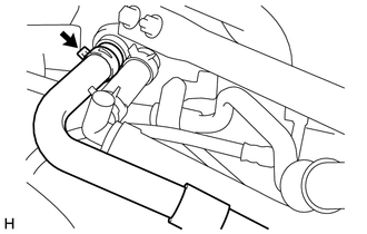
Using pliers, grip the claws of the clip and slide the clip to disconnect the inlet heater water hose A.
Note
-
Do not apply excessive force to the inlet heater water hose A.
-
Prepare a drain pan or cloth in case the coolant leaks.
-
Since the inlet heater water hose A must be installed in a predefined position, apply matching marks before removing it.
-
-
-
DISCONNECT OUTLET HEATER WATER HOSE A
-
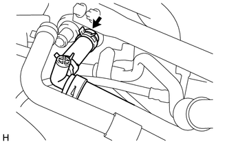
Using pliers, grip the claws of the clip and slide the clip to disconnect the outlet heater water hose A.
Note
-
Do not apply excessive force to the outlet heater water hose A.
-
Prepare a drain pan or cloth in case the coolant leaks.
-
Since the outlet heater water hose A must be installed in a predefined position, apply matching marks before removing it.
-
-
-
DISCONNECT SUCTION HOSE SUB-ASSEMBLY
-
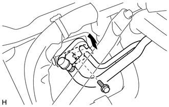
Remove the bolt and slide the hook connector.
-
Disconnect the suction hose sub-assembly.
-
Remove the O-ring from the suction hose sub-assembly.
Note
Seal the openings of the disconnected parts using vinyl tape to prevent entry of moisture and foreign matter.
-
-
DISCONNECT AIR CONDITIONER TUBE AND ACCESSORY ASSEMBLY
-
Disconnect the air conditioner tube and accessory assembly.
-
Remove the O-ring from the air conditioner tube and accessory assembly.
Note
Seal the openings of the disconnected parts using vinyl tape to prevent entry of moisture and foreign matter.
-
-
REMOVE INSTRUMENT PANEL SUB-ASSEMBLY
-
REMOVE LOWER NO. 1 INSTRUMENT PANEL AIR BAG ASSEMBLY (w/ Knee Airbag)
-
REMOVE STEERING COLUMN ASSEMBLY
-
REMOVE FRONT DOOR SCUFF PLATE LH
-
REMOVE FRONT DOOR SCUFF PLATE RH
-
REMOVE COWL SIDE TRIM BOARD LH
-
REMOVE COWL SIDE TRIM BOARD RH
-
REMOVE INSTRUMENT PANEL REINFORCEMENT ASSEMBLY
-
for Driver Side
-
Using a T20 "TORX" socket wrench, remove the 2 bolts.
Text in Illustration *1 "TORX" Bolt - - -
Remove the bolt.
-
Disconnect each connector and disengage the clamp and 2 claws.
-
-
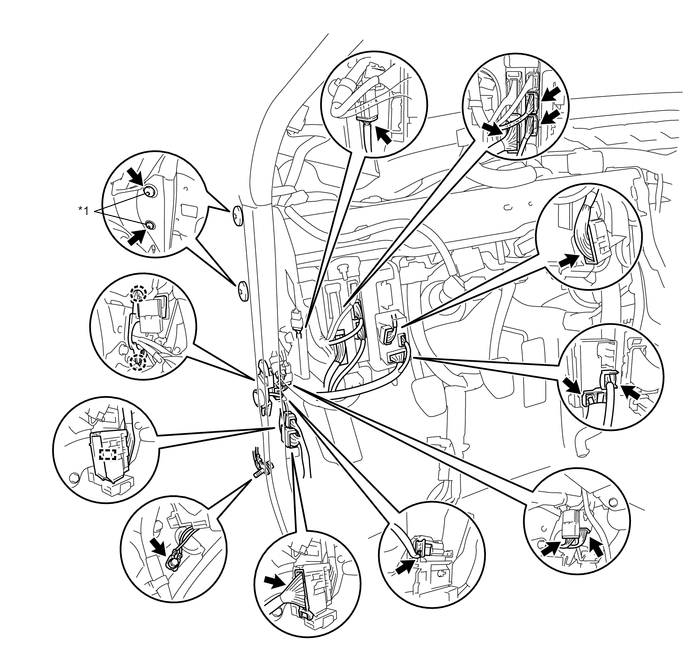
for Center Side
-
Remove the each bolts and disengage the clip.
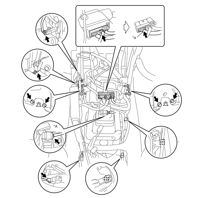
Text in Illustration *A for Automatic Air Conditioning System - - *a Disengage the lock plate and disconnect connector. - - -
Disconnect each connector and disengage the each clamp.
-
-
for Front Passenger Side
-
Using a T20 "TORX" socket wrench, remove the 2 bolts.
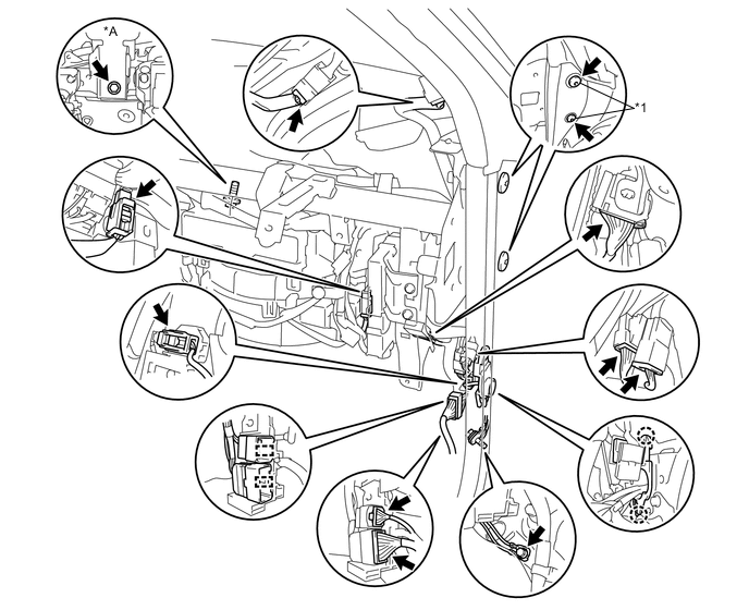
Text in Illustration *A for RHD - - *1 "TORX" Bolt - - -
Remove the each bolts.
-
Disconnect each connector and disengage the 2 clamps and 2 claws.
-
-
Remove the instrument panel reinforcement assembly.
-
-
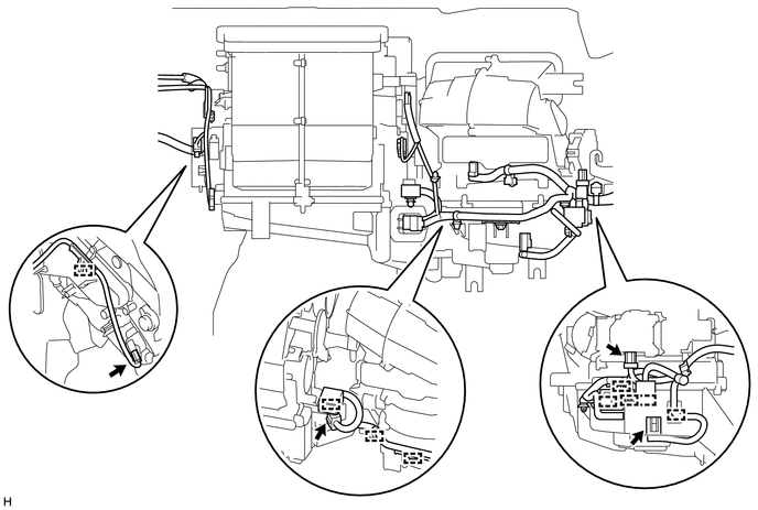
REMOVE AIR CONDITIONING UNIT ASSEMBLY (for Automatic Air Conditioning System)
-
Disconnect each connector and disengage each clamp.
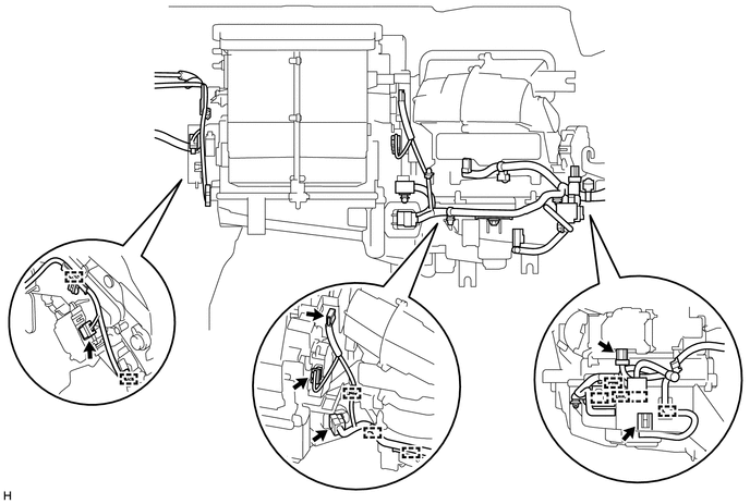
-
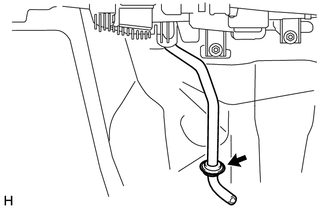
Disengage the drain cooler hose.
-
Remove the 3 bolts, 3 nuts and air conditioning unit assembly.
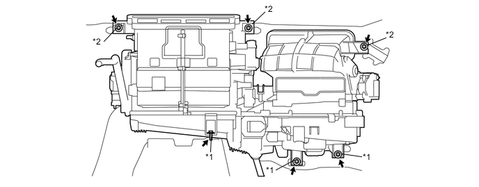
Text in Illustration *1 Bolt *2 Nut
-
-
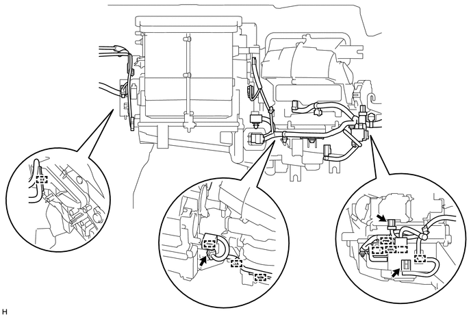
REMOVE AIR CONDITIONING UNIT ASSEMBLY (for Manual Air Conditioning System)
-
Disconnect each connector and disengage each clamp.
-
Disengage the drain cooler hose.
-
Remove the 3 bolts, 3 nuts and air conditioning unit assembly.
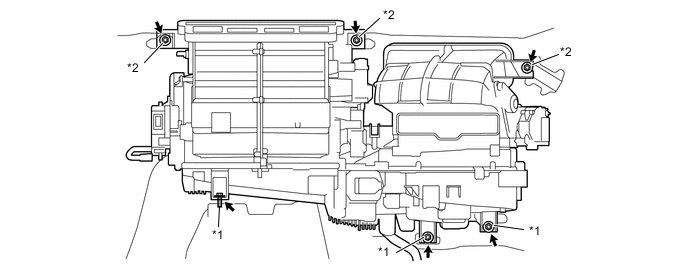
Text in Illustration *1 Bolt *2 Nut
-
-
REMOVE AIR CONDITIONING UNIT ASSEMBLY (w/o Air Conditioning System)
-
Disconnect each connector and disengage each clamp.
-
Disengage the drain cooler hose.
-
Remove the 3 bolts, 3 nuts and air conditioning unit assembly.
Text in Illustration *1 Bolt *2 Nut
-