CRUISE CONTROL SYSTEM(except 1WW) Clutch Switch Circuit
| DTC Code | DTC Name |
|---|---|
| Clutch Switch Circuit |
DESCRIPTION
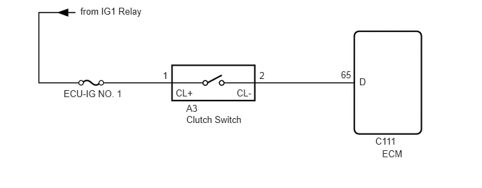
While depressing the clutch pedal, the clutch switch sends a signal to terminal 65 (D) of the ECM. The ECM cancels cruise control when terminal 65 (D) receives the signal.
WIRING DIAGRAM
CAUTION / NOTICE / HINT
Inspect the fuses for circuits related to this system before performing the following inspection procedure.
PROCEDURE
INSPECT CLUTCH SWITCH ASSEMBLY
for LHD:
Remove the clutch switch (Click here).
for RHD:
Remove the clutch switch (Click here).
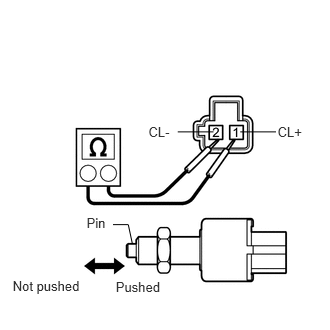
Measure the resistance according to the value(s) in the table below.
Standard Resistance
Tester Connection
Switch Condition
Specified Condition
1 (CL+) - 2 (CL-)
Pushed
Below 1 Ω
Not pushed
10 kΩ or higher
Table 1. Result Result
Proceed to
OK
A
NG (for LHD)
B
NG (for RHD)
C
CHECK HARNESS AND CONNECTOR (CLUTCH SWITCH - ECM AND BATTERY)
Disconnect the A3 switch connector.
Disconnect the C111 ECM connector.
Measure the voltage according to the value(s) in the table below.
Standard Voltage
Tester Connection
Switch Condition
Specified Condition
A3-1 (CL+) - Body ground
Ignition switch ON
11 to 14 V
Ignition switch off
Below 1 V
Measure the resistance according to the value(s) in the table below.
Standard Resistance
Tester Connection
Condition
Specified Condition
A3-2 (CL-) - C111-65 (D)
Always
Below 1 Ω
A3-2 (CL-) - Body ground
Always
10 kΩ or higher
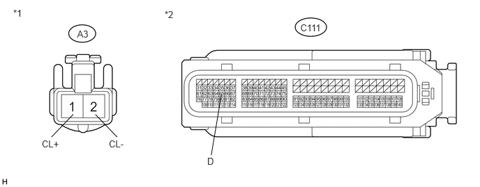
Table 2. Text in Illustration *1
Front view of wire harness connector
(to Clutch Switch)
*2
Front view of wire harness connector
(to ECM)
REPAIR OR REPLACE HARNESS OR CONNECTOR