WIPER AND WASHER SYSTEM Washer Signal Circuit
| DTC Code | DTC Name |
|---|---|
| Washer Signal Circuit |
DESCRIPTION
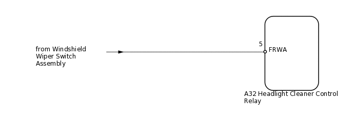
The headlight cleaner control relay receives the windshield washer operation signal.
WIRING DIAGRAM
PROCEDURE
CHECK OPERATION
Check the operation of the front wiper and washer system.
OK
Front wiper and washer system operates normally.
Result
Result
OK
NG
CHECK HARNESS AND CONNECTOR (WINDSHIELD WIPER SWITCH ASSEMBLY - HEADLIGHT CLEANER CONTROL RELAY)
-
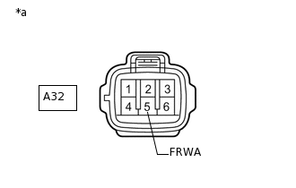
*a
Front view of wire harness connector
(to Headlight Cleaner Control Relay)
Disconnect the A32 headlight cleaner control relay connector.
Measure the voltage according to the value(s) in the table below.
Standard Voltage
Tester Connection
Switch Condition
Specified Condition
A32-5 (FRWA) - Body ground
Engine switch on (IG), front washer switch on
Below 1 V
A32-5 (FRWA) - Body ground
Engine switch on (IG), front washer switch off
11 to 14 V
Result
Result
OK
NG
NG REPAIR OR REPLACE HARNESS OR CONNECTOR
-