ДВИГАТЕЛЬ ПРОВЕРКА БЕЗ СНЯТИЯ С АВТОМОБИЛЯ

-
INSPECT COOLANT
-
INSPECT ENGINE OIL
-
INSPECT BATTERY SPECIFIC GRAVITY
-
INSPECT AIR CLEANER FILTER ELEMENT SUB-ASSEMBLY
-
Remove the air cleaner filter element from the air cleaner case sub-assembly.
-
Visually check that there is no dirt, clog, and damage to the air cleaner filter element.
Tech Tips
-
If there is any dirt or clog on the air cleaner filter element, clean it with compressed air.
-
If any dirt or clog remains even after cleaning the air cleaner element with compressed air, replace it.
-
-
-
INSPECT VANE PUMP V BELT
-
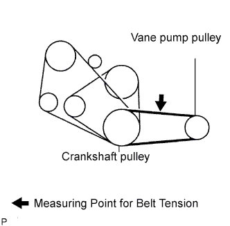
Check the V belt deflection.
-
Belt deflection
Pressing force 98 N (10 kgf, 22 *lbf) New belt
mm (in.)
Used belt
mm (in.)
7.5 to 9.5
(0.30 to 0.37)
9.0 to 13
(0.35 to 0.51)
-
Tension
New belt
N (kgf)
Used belt
N (kgf)
441 to 539
(45 to 55)
245 to 343
(25 to 35)
Note
-
Check the drive belt deflection at the specified point.
-
When installing a new belt, set its tension value as specified.
-
When checking a belt used for over 5 minutes, confirm the deflection value is within the specified range.
-
When reinstalling a belt used for over 5 minutes, perform the check based on the used deflection value.
-
V belt tension and deflection value should be checked after two revolution of engine cranking.
-
When using a belt tension gauge, confirm the accuracy first by using a master gauge.
-
-
-
-
INSPECT V (COOLER COMPRESSOR TO CRANKSHAFT PULLEY) BELT NO.1 (W/ AIR CONDITIONING)
-
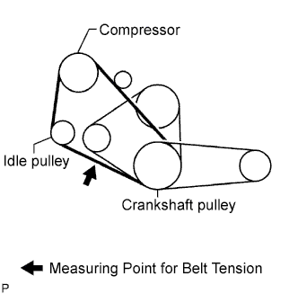
Check the V belt deflection.
-
Belt deflection
Pressing force 98 N (10 kgf, 22 *lbf) New belt
mm (in.)
Used belt
mm (in.)
11 to 15
(0.43 to 0.59)
15 to 20
(0.59 to 0.79)
-
Tension
New belt
N (kgf)
Used belt
N (kgf)
372 to 608
(38 to 62)
196 to 392
(20 to 40)
Note
-
Check the drive belt deflection at the specified point.
-
When installing a new belt, set its tension value as specified.
-
When checking a belt used for over 5 minutes, confirm the deflection value is within the specified range.
-
When reinstalling a belt used for over 5 minutes, perform the check based on the used deflection value.
-
V belt tension and deflection value should be checked after two revolution of engine cranking.
-
When using a belt tension gauge, confirm the accuracy first by using a master gauge.
-
-
-
-
INSPECT FAN & GENERATOR V BELT
-
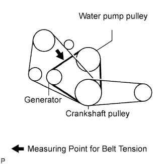
Check the V belt deflection. (Per 1 belt)
-
Belt deflection
Pressing force 98 N (10 kgf, 22 *lbf) New belt
mm (in.)
Used belt
mm (in.)
7.0 to 10
(0.28 to 0.39)
10 to 14
(0.39 to 0.55)
-
Tension (Per 1 belt)
New belt
N (kgf)
Used belt
N (kgf)
441 to 539
(45 to 55)
196 to 343
(20 to 35)
Note
-
Check the drive belt deflection at the specified point.
-
When installing a new belt, set its tension value as specified.
-
When checking a belt used for over 5 minutes, confirm the deflection value is within the specified range.
-
When reinstalling a belt used for over 5 minutes, perform the check based on the used deflection value.
-
V belt tension and deflection value should be checked after two revolution of engine cranking.
-
When using a belt tension gauge, confirm the accuracy first by using a master gauge.
-
-
-
-
INSPECT INJECTION TIMING
-
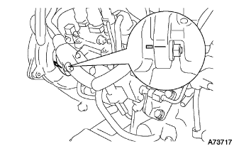
Using a mirror, check that the matchmarks of the injection pump flange and the timing gear case are aligned.
-
-
ADJUST INJECTION TIMING
-
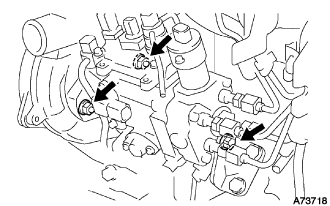
Loosen the following nuts and bolts.
-
Bolt holding the injection pump to the injection pump stay.
-
2 nuts holding the injection pump to the timing gear case.
-
-
Align the matchmark by slightly tilting the injection pump.
-
Tighten the following nuts and bolts.
-
2 nuts holding the injection pump to the timing gear case.
- Torque:
- 21 N*m { 210 kgf*cm, 15 ft.*lbf }
-
Bolt holding the injection pump to the injection pump stay.
- Torque:
- 26 N*m { 270 kgf*cm, 19 ft.*lbf }
-
-
-
INSPECT ENGINE IDLE SPEED
-
Warm up the engine.
-
When using an intelligent tester:
-
Connect the intelligent tester to the DLC3.
Idle speed 720 to 820 rpm (A/C OFF) 750 to 850 rpm (A/C ON) Tech Tips
Refer to the intelligent tester operator's manual for further details.
-
-
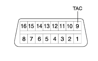
When not using an intelligent tester:
-
Using SST, connect the tachometer test probe to terminal 9 (TAC) of the DLC3.
- SST
- 09843-18040
-
Check the idle speed.
Idle speed 720 to 820 rpm (A/C OFF) 750 to 850 rpm (A/C ON) Note
Switch off all accessories.
-
-
-
INSPECT MAXIMUM ENGINE SPEED
-
Start the engine.
-
Depress the accelerator pedal all the way.
-
Check the maximum speed.
Maximum speed 4,850 to 4,950 rpm
-
-
INSPECT COMPRESSION
Tech Tips
If there is a lack of power, excessive oil consumption or poor fuel economy is suspected. Measure the compression pressure.
-
Warm up and stop the engine.
-
Remove the glow plugs. Click here
-
Disconnect the spill control valve connector.
-
Check the cylinder compression pressure.
Tech Tips
Turn the starter before measuring the compression pressure and remove the foreign objects.
-
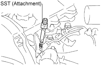
Install SST (attachment) to the glow plug hole.
- SST
- 09992-00025 ( 09992-00121 )
- Torque:
- 13 N*m { 133 kgf*cm, 10 ft.*lbf }
-
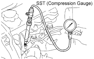
Connect SST (compression gauge) to the SST (attachment).
- SST
- 09992-00025 ( 09992-00211 )
-
Fully open the throttle valve, and start the engine.
-
While cranking the engine, measure the compression pressure.
Tech Tips
Always use a fully charged battery to obtain engine revolution of 250 rpm or more.
-
Repeat steps (a) through (d) for each cylinder.
Note
This measurement must be done as quickly as possible.
Compression pressure 3,138 kPa (32.0 kgf/cm2, 455 psi) or more Minimum pressure 1,961 kPa (20.0 kgf/cm2, 284 psi) Difference between each cylinder 490 kPa (5.0 kgf/cm2, 71 psi) or less -
If the cylinder compression in one or more cylinders is low, pour a small amount of engine oil into the cylinder through the glow plug hole and repeat steps (a) through (d) for the cylinder with low compression.
-
If adding oil helps the compression, the piston rings and/or cylinder bore may be worn or damaged.
-
If pressure stays low, a valve may be stuck or the seating may be improper, or there may be leakage past the gasket.
-
-
Remove the SST.
-
Reinstall the glow plugs. Click here
-
Reconnect the spill control valve connector.
-