ДОПОЛНИТЕЛЬНАЯ ФОРСУНКА ОТРАБОТАВШЕГО ТОПЛИВА УСТАНОВКА
-
INSTALL EXHAUST FUEL ADDITION INJECTOR ASSEMBLY
-
Install a new No. 1 fuel injector back-up ring, No. 2 fuel injector back-up ring, O-ring and No. 3 fuel injector back-up ring to the exhaust fuel addition injector assembly.
-
Install a new E-ring to the exhaust fuel addition injector assembly.
-
Install a new gasket and the exhaust fuel addition injector assembly to the No. 1 injector holder.
-
-
INSTALL NO. 2 NOZZLE HOLDER CLAMP
-
Using a T40 "TORX" socket wrench, install the No. 2 nozzle holder clamp with the bolt.
- Torque:
- 12 N*m { 117 kgf*cm, 8 ft.*lbf }
-
-
INSTALL INJECTOR HOLDER
-
Install the injector holder to the No. 1 injector holder with the 2 bolts.
- Torque:
- 10 N*m { 102 kgf*cm, 7 ft.*lbf }
-
-
INSTALL NO. 2 EXHAUST MANIFOLD HEAT INSULATOR
-
Install a new gasket and the No. 2 exhaust manifold heat insulator to the No. 1 injector holder with the 3 nuts.
- Torque:
- 10 N*m { 102 kgf*cm, 7 ft.*lbf }
-
-
INSTALL NO. 1 INJECTOR HOLDER
-
Install the No. 1 injector holder to the exhaust manifold with 3 new nuts.
- Torque:
- 43 N*m { 438 kgf*cm, 32 ft.*lbf }
-
Connect the connector to the exhaust fuel addition injector assembly.
-
-
CONNECT NO. 5 WATER BY-PASS HOSE
-
Connect the No. 5 water by-pass hose to the No. 1 injector holder, and slide the clamp to secure the hose.
-
-
CONNECT NO. 4 WATER BY-PASS HOSE
-
Connect the No. 4 water by-pass hose to the No. 1 injector holder, and slide the clamp to secure the hose.
-
-
INSTALL NO. 1 FUEL PIPE
-
Connect the No. 1 fuel pipe to the No. 4 fuel pipe.
-
Install a new gasket and the No. 1 fuel pipe to the cylinder head cover sub-assembly and No. 1 injector holder with the union bolt and bolt.
- Torque:
- for bolt
- 10 N*m { 102 kgf*cm, 7 ft.*lbf }
- for union bolt
- 26 N*m { 265 kgf*cm, 19 ft.*lbf }
-
-
INSTALL ENGINE SERVICE HOLE SUB COVER SUB-ASSEMBLY
-
Install the engine service hole sub cover sub-assembly with the 5 bolts.
- Torque:
- 13 N*m { 133 kgf*cm, 10 ft.*lbf }
-
Return the floor carpet to its original position.
-
-
INSTALL FRONT DOOR SCUFF PLATE RH
-
INSTALL FRONT SEAT ASSEMBLY RH
-
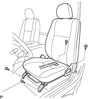
Подсоедините разъем замка ремня безопасности переднего сиденья в сборе и установите переднее сиденье в сборе.
-
Совместите штырь регулятора переднего сиденья в сборе с отверстиями в кузове.
-
Сдвиньте переднее сиденье в сборе в крайнее заднее положение.
Note
Убедитесь, что переднее сиденье в сборе надежно зафиксировано.
-
Предварительно затяните 2 болта на передней стороне переднего сиденья в сборе.
-
Выдвиньте переднее сиденье в сборе до упора вперед.
Note
Убедитесь, что переднее сиденье в сборе надежно зафиксировано.
-
Предварительно затяните 2 болта на задней стороне переднего сиденья в сборе.
-
Сдвиньте переднее сиденье в сборе в крайнее заднее положение.
Note
Убедитесь, что переднее сиденье в сборе надежно зафиксировано.
-
Полностью затяните 2 болта на передней стороне переднего сиденья в сборе, сначала наружный, а затем внутренний.
- Torque:
- 39 Н*м { 398 кгс*см, 29 фунт-сила-футов }
-
Выдвиньте переднее сиденье в сборе до упора вперед.
Note
Убедитесь, что переднее сиденье в сборе надежно зафиксировано.
-
Полностью затяните 2 болта на задней стороне переднего сиденья в сборе, сначала наружный, а затем внутренний.
- Torque:
- 39 Н*м { 398 кгс*см, 29 фунт-сила-футов }
-
-
INSTALL SEAT TRACK COVER LH
-
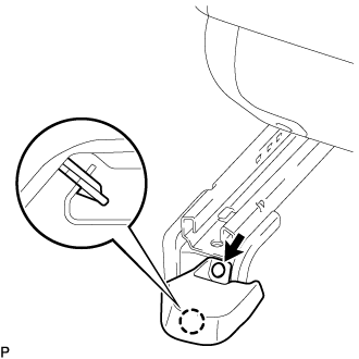
Введите в зацепление захват и установите новый щиток направляющей левого сиденья и закрепите новым фиксатором.
-
-
BLEED AIR FROM FUEL SYSTEM
-
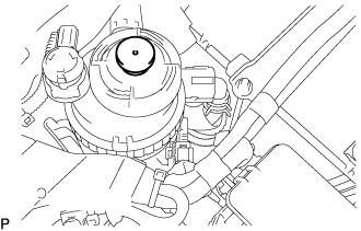
Using the hand pump mounted on the fuel filter cap, bleed air from the fuel system. Continue pumping until the pump resistance increases.
Note
-
The maximum hand pump pumping speed is 2 strokes per second.
-
The hand pump must be pushed with a full stroke during pumping.
-
When the fuel pressure at the supply pump inlet port reaches a saturated pressure, the hand pump resistance increases.
-
If pumping is interrupted during the air bleeding process, fuel in the fuel line may return to the fuel tank. Continue pumping until the hand pump resistance increases.
-
If the hand pump resistance does not increase despite consecutively pumping 200 times or more, there may be a fuel leak between the fuel tank and fuel filter, the hand pump may be malfunctioning, or the vehicle may have run out of fuel.
-
If air bleeding using the hand pump is incomplete, the common rail pressure does not rise to the pressure range necessary for normal use and the engine cannot be started.
-
-
Check if the engine starts.
Note
-
Even if air bleeding using the hand pump has been completed, the starter may need to be cranked for 10 seconds or more to start the engine.
-
Do not crank the engine continuously for more than 20 seconds. The battery may be discharged.
-
Use a fully-charged battery.
-
When the engine can be started, proceed to the next step.
-
If the engine cannot be started, bleed air again using the hand pump until the hand pump resistance increases (refer to the procedures above). Then start the engine.
-
-
Turn the ignition switch off.
-
Connect the GTS to the DLC3.
-
Turn the ignition switch to ON and turn the GTS on.
-
Clear the DTCs Click here.
-
Start the engine.*1
-
Enter the following menus: Powertrain / Engine and ECT / Active Test / Test the Fuel Leak.*2
-
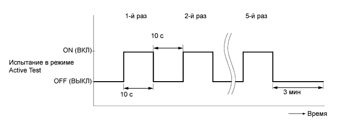
Perform the following test 5 times with on/off intervals of 10 seconds: Active Test / Test the Fuel Leak.*3
-
Allow the engine to idle for 3 minutes or more after performing the Active Test for the 5th time.
Tech Tips
When the Active Test "Test the Fuel Leak" is used to change the pump control mode, the actual fuel pressure inside the common rail drops below the target fuel pressure when the Active Test is off, but this is normal and does not indicate a pump malfunction.
-
Enter the following menus: Powertrain / Engine and ECT /Trouble Codes.
-
Read Current DTCs.
-
Clear the DTCs Click here.
Tech Tips
It is necessary to clear the DTCs as DTC P1604 or P1605 may be stored when air is bled from the fuel system after replacing or repairing fuel system parts.
-
Repeat steps *1 to *3.
-
Enter the following menus: Powertrain / Engine and ECT / Trouble Codes.
-
Read Current DTCs.
OK No DTCs are output.
-
-
ADD ENGINE COOLANT
-
Надежно затяните сливные пробки.
-
Залейте в расширительный бачок системы охлаждения охлаждающую жидкость двигателя до верха горловины.
Номинальный объем 13,9 л (14,6 кварты США, 12,2 английской кварты) Note
Не доливайте простую воду вместо охлаждающей жидкости двигателя.
Tech Tips
-
Использование неподходящей охлаждающей жидкости может привести к повреждению системы охлаждения двигателя.
-
Разрешается использовать только охлаждающую жидкость "TOYOTA Super Long Life Coolant (SLLC)" или аналогичную высококачественную охлаждающую жидкость на основе этиленгликоля (не на силикатной, аминовой, нитритной или борнокислой основе), изготовленную по гибридной технологии органических кислот с длительным сроком годности (охлаждающая жидкость, изготовленная по гибридной технологии органических кислот с длительным сроком годности, состоит из низкофосфатных соединений и органических кислот).
-
-
Ослабьте прокачной штуцер выпускного патрубка охлаждающей жидкости в сборе.
-
После удаления воздуха и слива охлаждающей жидкости двигателя надежно затяните прокачной штуцер.
- Torque:
- 8,0 Н*м { 82 кгс*см, 71 фунт-сила-дюйм }
-

Долейте охлаждающую жидкость двигателя в расширительный бачок системы охлаждения до отметки B и установите пробку радиатора.
-
Прогревайте двигатель, пока не откроется термостат.
-
Когда термостат откроется, несколько минут прокачивайте охлаждающую жидкость двигателя.
Tech Tips
Время открывания термостата можно проверить, сжав шланг радиатора № 3 рукой и определив, когда охлаждающая жидкость начинает поступать в шланг.
-
-
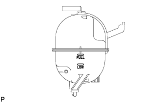
После охлаждения двигателя убедитесь, что уровень охлаждающей жидкости двигателя находится между отметками "LOW" и "FULL".
-
-
INSPECT FOR COOLANT LEAK
CAUTION:
Не снимайте пробку радиатора, пока двигатель и радиатор не остынут. Выброс горячей охлаждающей жидкости и пара под давлением может стать причиной серьезных ожогов.
-
Заполните радиатор охлаждающей жидкостью и подсоедините к радиатору приспособление для опрессовки системы охлаждения и проверки пробки радиатора.
-
Прогрейте двигатель.
-
С помощью приспособления для опрессовки системы охлаждения и проверки пробки радиатора увеличьте давление в радиаторе до 137 кПа (1,4 кгс/см2, 19,9 фунтов на кв. дюйм) и убедитесь, что давление не падает.
Tech Tips
Если давление снижается, проверьте на наличие утечек шланги, радиатор в сборе и насос системы охлаждения двигателя в сборе. При отсутствии внешних утечек проверьте сердцевину отопителя, блок цилиндров в сборе и головку блока цилиндров в сборе.
-