PROPELLER SHAFT ASSEMBLY (for TSAM Made) REASSEMBLY
-
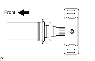
INSTALL CENTER NO. 1 SUPPORT BEARING ASSEMBLY
-
Install the center support bearing to the intermediate shaft.
-
Coat the splines of the intermediate shaft with MP grease.
-
Install the washer.
-
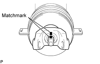
Align the matchmarks on the center yoke and intermediate shaft, and then install the yoke to the shaft.
-
Install the washer.
-
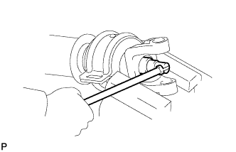
Clamp the center yoke in a vise between aluminum plates and press the bearing into position by tightening a new nut.
- Torque:
- 181 N*m { 1850 kgf*cm, 134 ft.*lbf }
-
Loosen the nut.
-
Torque the nut again.
- Torque:
- 82 N*m { 836 kgf*cm, 60 ft.*lbf }
-
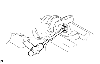
Using a chisel and hammer, stake the lock nut.
-
-
INSTALL UNIVERSAL JOINT SPIDER ASSEMBLY
Tech Tips
Install the other universal joint spider(s) using the samse procedures.
-
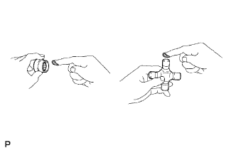
Apply MP grease to a new spider and bearings.
-
Fit the spider into the flange yoke.
-
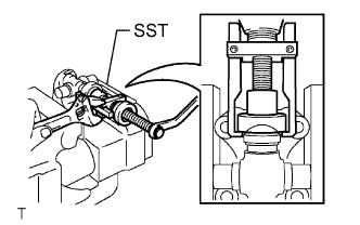
Using SST, install the spider bearings to the spider.
- SST
- 09332-25010
-
Using SST, adjust the spider bearings so that: 1) the yoke does not overlap the snap ring grooves of the spider bearings; 2) the grooves are as wide as possible; and 3) the groove width on both sides is the same.
- SST
- 09332-25010
-
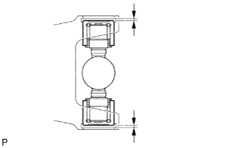
Install 2 new snap rings to the installed spider bearings. The snap rings must have equal thickness which will allow 0 to 0.05 mm (0 to 0.00197 in.) of axial play.
Standard Snap Ring Thickness Part No. Thickness Color 90080-52174 1.38 mm (0.0543 in.) Green 90080-52044 1.384 mm (0.0545 in.) Green 90080-52043 1.435 mm (0.0565 in.) Purple 90080-52175 1.45 mm (0.0571 in.) Orange 90080-52176 1.48 mm (0.0583 in.) Black 90080-52041 1.486 mm (0.0585 in.) Black 90080-52176 1.48 mm (0.0583 in.) Black 90080-52042 1.511 mm (0.0595 in.) Copper 90080-52040 1.537 mm (0.0605 in.) Silver 90080-52178 1.54 mm (0.0606 in.) Yellow 90080-52039 1.588 mm (0.0625 in.) Yellow 90080-52179 1.63 mm (0.0642 in.) Red 90080-52038 1.638 mm (0.0645 in.) Blue 90080-52180 1.68 mm (0.0661 in.) Blue 90080-52156*
1.49 mm (0.0587 in.) - *: For cup with grease nipple. Note
-
New snap rings must be used.
-
The snap ring thickness must be the same on both ends.
-
-
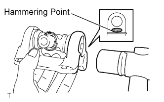
Using a hammer, tap the flange yoke until there is no clearance between the spider bearings and snap rings.
-
Align the matchmarks on the yoke and shaft (or center yoke and sleeve yoke), and install the yoke together with the spider.
-
Install the 2 remaining spider bearings.
-
-
INSTALL REAR SLIDING SHAFT BOOT (for 4WD)
-
Temporarily install a new boot (with 2 new clamps) to the propeller shaft.
-
Mount the propeller shaft in a soft vice.
-
Coat the splines of the propeller shaft with MP grease.
-
Align the matchmarks on the propeller shaft and sleeve yoke.
-
Install the sleeve yoke to the propeller shaft and connect the boot.
-
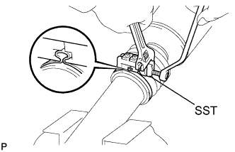
Secure one of the boot clamps onto the boot.
-
Place SST onto the boot clamp.
- SST
- 09521-24010
-
Tighten SST so that the boot clamp is pinched as shown in the illustration.
Note
Do not overtighten SST.
-
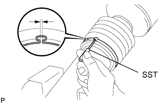
Using SST, adjust the clearance of the boot clamp.
- SST
- 09240-00020
Standard clearance 0.8 mm (0.0315 in.) or less
-
-
For the remaining boot clamp, use the same procedures described above.
-
-
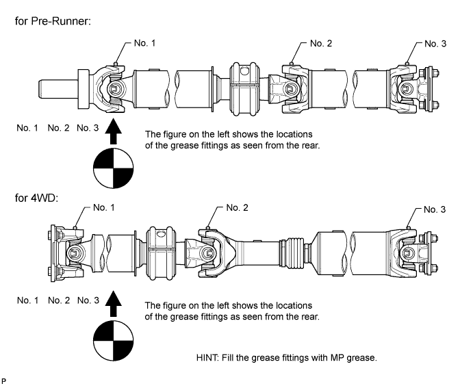
INSPECT REAR PROPELLER SHAFT ASSEMBLY (for 4WD)
-
When the spider bearing is replaced, be sure that the grease fittings are facing the direction shown in the illustration.
-
-
INSPECT UNIVERSAL JOINT SPIDER ASSEMBLY
-
Check the spider bearings for wear or damage.
-
Check each spider bearing axial play by turning the yoke while holding the shaft tightly.
Maximum bearing axial play 0.05 mm (0.00197 in.) If the bearing axial play is greater than the maximum, replace the spider bearing.
-