PRE-COLLISION SYSTEM TERMINALS OF ECU
CHECK PRE-COLLISION CITY SENSOR

Disconnect the Q12 pre-collision city sensor connector.
Note:DTCs may be output when connectors are disconnected during inspection. Therefore, be sure to clear the DTCs using the GTS once the inspection has been completed.
Do not apply excessive force to the Q12 pre-collision city sensor connector.
Measure the voltage and resistance according to the value(s) in the table below.
Terminal No. (Symbol)
Wiring Color
Terminal Description
Condition
Specified Condition
Q12-8 (BUZ) - Q12-10 (GND)
GR - W-B
Pre-collision city buzzer operation signal
Ignition switch ON, pre-collision city buzzer not operating
11 to 14 V
Ignition switch ON, pre-collision city buzzer operating
0 to 1.5 V
Q12-9 (PCSW) - Q12-10 (GND)
B - W-B
Pre-collision system cancel switch signal
Pre-collision system cancel switch being pressed
Below 1 Ω
Pre-collision system cancel switch not being pressed
100 kΩ or higher
Q12-7 (IG1) - Q12-10 (GND)
L - W-B
Power source
Ignition switch ON
11 to 14 V
Ignition switch off
Below 1 V
Q12-10 (GND) - Body ground
W-B - Body ground
Ground
Always
Below 1 Ω
Tip:If the result is not as specified, there may be a malfunction on the wire harness side.
Reconnect the Q12 pre-collision city sensor connector.
Check for pulses according to the value(s) in the table below.
Terminal No. (Symbol)
Wiring Color
Terminal Description
Condition
Specified Condition
Q12-5 (CA1P) - Q12-10 (GND)
R - W-B
CAN communication signal
Ignition switch ON
Pulse generation
(See waveform 1)
Q12-11 (CA1N) - Q12-10 (GND)
W - W-B
CAN communication signal
Ignition switch ON
Pulse generation
(See waveform 1)
-
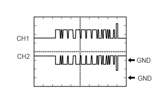
Waveform 1
CAN communication signal
Item
Content
Tester Connection
CH1: Q12-5 (CA1P) - Q12-10 (GND)
CH2: Q12-11 (CA1N) - Q12-10 (GND)
Tool Setting
1 V/DIV., 50 μsec./DIV.
Condition
Ignition switch ON
Tip:If the result is not as specified, the CAN bus line, terminating resistor circuit (or part with this circuit) or pre-collision city sensor is malfunctioning.