INPUT SHAFT INSPECTION
PROCEDURE
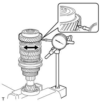
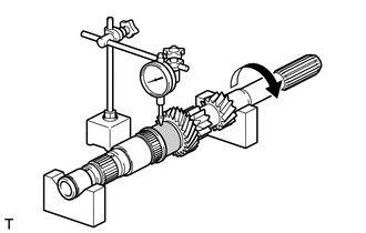
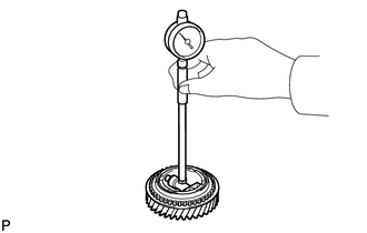
INSPECT 6TH GEAR THRUST CLEARANCE
-
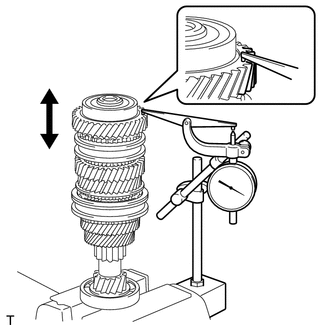
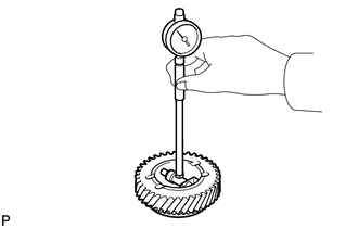
Using a dial indicator, measure the 6th gear thrust clearance.
Standard clearance
0.20 to 0.47 mm (0.00788 to 0.01850 in.)
Maximum clearance
0.47 mm (0.01850 in.)
If the clearance is more than the maximum, replace the No. 3 transmission clutch hub, 6th gear or input shaft. Replace the part or parts determined to be the most likely cause of the problem.
-
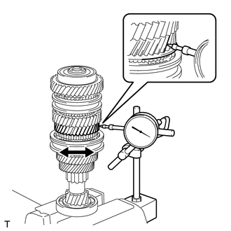
INSPECT 5TH GEAR THRUST CLEARANCE
-
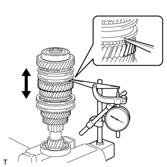
Using a dial indicator, measure the 5th gear thrust clearance.
Standard clearance
0.20 to 0.47 mm (0.00788 to 0.01850 in.)
Maximum clearance
0.47 mm (0.01850 in.)
If the clearance is more than the maximum, replace the No. 3 transmission clutch hub, 5th gear or input shaft. Replace the part or parts determined to be the most likely cause of the problem.
-
INSPECT 4TH GEAR THRUST CLEARANCE
-
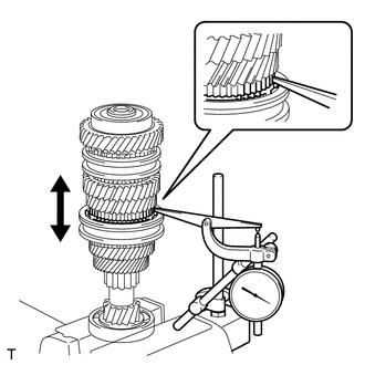
Using a dial indicator, measure the 4th gear thrust clearance.
Standard clearance
0.13 to 0.60 mm (0.00512 to 0.02362 in.)
Maximum clearance
0.60 mm (0.02362 in.)
If the clearance is more than the maximum, replace the No. 2 transmission clutch hub, 4th gear or input shaft. Replace the part or parts determined to be the most likely cause of the problem.
-
INSPECT 3RD GEAR THRUST CLEARANCE
-
Using a dial indicator, measure the 3rd gear thrust clearance.
Standard clearance
0.20 to 0.47 mm (0.00788 to 0.01850 in.)
Maximum clearance
0.47 mm (0.01850 in.)
If the clearance is more than the maximum, replace the No. 2 transmission clutch hub, 3rd gear or input shaft. Replace the part or parts determined to be the most likely cause of the problem.
-
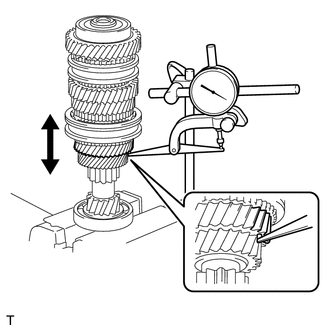
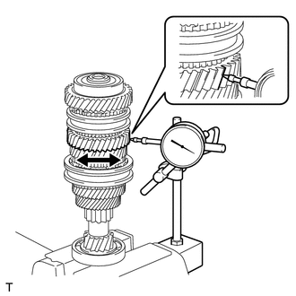
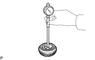
INSPECT 6TH GEAR RADIAL CLEARANCE
-
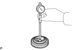
Using a dial indicator, measure the 6th gear radial clearance between the gear and shaft.
Standard clearance
0.009 to 0.045 mm (0.00036 to 0.00177 in.)
Maximum clearance
0.045 mm (0.00177 in.)
If the clearance is more than the maximum, replace the 6th gear, 6th gear needle roller bearing, inner 6th gear bearing race or input shaft. Replace the part or parts determined to be the most likely cause of the problem.
-
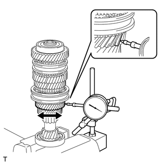
INSPECT 5TH GEAR RADIAL CLEARANCE
-
Using a dial indicator, measure the 5th gear radial clearance between the gear and shaft.
Standard clearance
0.009 to 0.045 mm (0.00036 to 0.00177 in.)
Maximum clearance
0.045 mm (0.00177 in.)
If the clearance is more than the maximum, replace the 5th gear, 5th gear needle roller bearing, inner 5th gear bearing race or input shaft. Replace the part or parts determined to be the most likely cause of the problem.
-
INSPECT 4TH GEAR RADIAL CLEARANCE
-
Using a dial indicator, measure the 4th gear radial clearance between the gear and shaft.
Standard clearance
0.009 to 0.036 mm (0.00036 to 0.00141 in.)
Maximum clearance
0.036 mm (0.00141 in.)
If the clearance is more than the maximum, replace the 4th gear, 4th gear needle roller bearing or input shaft. Replace the part or parts determined to be the most likely cause of the problem.
-
INSPECT 3RD GEAR RADIAL CLEARANCE
-
Using a dial indicator, measure the 3rd gear radial clearance.
Standard clearance
0.009 to 0.047 mm (0.00036 to 0.00185 in.)
Maximum clearance
0.047 mm (0.00185 in.)
If the clearance is more than the maximum, replace the 3rd gear, 3rd gear needle roller bearing or input shaft. Replace the part or parts determined to be the most likely cause of the problem.
-
INSPECT INPUT SHAFT
-
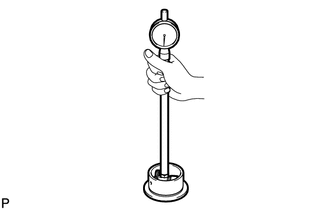
Using a dial indicator, measure the input shaft runout.
Maximum runout
0.03 mm (0.00118 in.)
If the runout is more than the maximum, replace the input shaft.
-
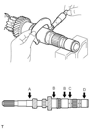
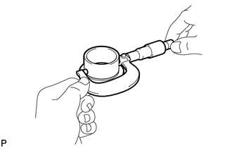
Using a micrometer, measure the outer diameter of the input shaft journal surface at the locations indicated.
Standard journal diameter
Journal A
27.608 to 27.620 mm (1.0870 to 1.0873 in.)
Journal B
41.290 to 41.300 mm (1.6256 to 1.6259 in.)
Journal C
38.280 to 38.300 mm (1.5071 to 1.5078 in.)
Journal D
35.490 to 35.500 mm (1.3973 to 1.3976 in.)
Minimum journal diameter
Journal A
27.608 mm (1.0870 in.)
Journal B
41.290 mm (1.6256 in.)
Journal C
38.280 mm (1.5071 in.)
Journal D
35.490 mm (1.3973 in.)
If the outer diameter is less than the minimum, replace the input shaft.
-
INSPECT INNER 6TH GEAR BEARING RACE
-
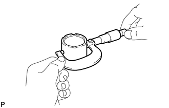
Using a micrometer, measure the outer diameter of the inner 6th gear bearing race.
Standard outer diameter
42.290 to 42.300 mm (1.6650 to 1.6653 in.)
Minimum outer diameter
42.290 mm (1.6650 in.)
If the outer diameter is less than the minimum, replace the inner 6th gear bearing race.
-
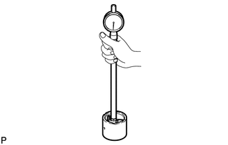
Using a cylinder gauge, measure the inside diameter of the inner 6th gear bearing race.
Standard inside diameter
35.500 to 35.515 mm (1.3977 to 1.3982 in.)
Maximum inside diameter
35.515 mm (1.3982 in.)
If the inside diameter is more than the maximum, replace the inner 6th gear bearing race.
-
INSPECT INNER 5TH GEAR BEARING RACE
-
Using a micrometer, measure the outer diameter of the inner 5th gear bearing race.
Standard outer diameter
45.290 to 45.300 mm (1.7831 to 1.7834 in.)
Minimum outer diameter
45.290 mm (1.7831 in.)
If the outer diameter is less than the minimum, replace the inner 5th gear bearing race.
-
Using a cylinder gauge, measure the inside diameter of the inner 5th gear bearing race.
Standard inside diameter
38.300 to 38.315 mm (1.5079 to 1.5084 in.)
Maximum inside diameter
38.315 mm (1.5084 in.)
If the inside diameter is more than the maximum, replace the inner 5th gear bearing race.
-
INSPECT 6TH GEAR SUB-ASSEMBLY
-
Using a cylinder gauge, measure the inside diameter of the 6th gear.
Standard inside diameter
47.309 to 47.325 mm (1.8626 to 1.8631 in.)
Maximum inside diameter
47.325 mm (1.8631 in.)
If the inside diameter is more than the maximum, replace the 6th gear.
-
INSPECT 5TH GEAR
-
Using a cylinder gauge, measure the inside diameter of the 5th gear.
Standard inside diameter
50.309 to 50.325 mm (1.9807 to 1.9812 in.)
Maximum inside diameter
50.325 mm (1.9812 in.)
If the inside diameter is more than the maximum, replace the 5th gear.
-
INSPECT 4TH GEAR
-
Using a cylinder gauge, measure the inside diameter of the 4th gear sub-assembly.
Standard inside diameter
47.301 to 47.317 mm (1.8623 to 1.8628 in.)
Maximum inside diameter
47.317 mm (1.8628 in.)
If the inside diameter is more than the maximum, replace the 4th gear.
-
INSPECT 3RD GEAR
-
Using a cylinder gauge, measure the inside diameter of the 3rd gear sub-assembly.
Standard inside diameter
47.309 to 47.325 mm (1.8626 to 1.8631 in.)
Maximum inside diameter
47.325 mm (1.8631 in.)
If the inside diameter is more than the maximum, replace the 3rd gear sub-assembly.
-
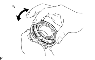
INSPECT NO. 5 SYNCHRONIZER RING
-
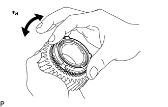
*a
Locks in both directions
Check for wear and damage.
Coat the 6th gear cone with gear oil.
Coat the 5th gear cone with gear oil.
Turn the No. 5 synchronizer ring in both directions while pushing it against the 6th gear cone and check that it locks in both directions.
If the No. 5 synchronizer ring does not lock, replace the No. 5 synchronizer ring.
Turn the No. 5 synchronizer ring in both directions while pushing it against the 5th gear cone and check that it locks in both directions.
If the No. 5 synchronizer ring does not lock, replace the No. 5 synchronizer ring.
-
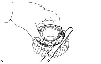
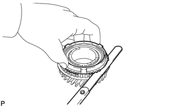
Using a feeler gauge, measure the clearance between the No. 5 synchronizer ring and gear spline end.
Standard clearance
0.88 to 1.52 mm (0.0347 to 0.0598 in.)
Minimum clearance
0.88 mm (0.0347 in.)
If the clearance is less than the minimum, replace the No. 5 synchronizer ring.
-
INSPECT NO. 4 SYNCHRONIZER RING
-
*a
Locks in both directions
Check for wear and damage.
Coat the 4th gear cone with gear oil.
Turn the No. 4 synchronizer ring in both directions while pushing it against the 4th gear cone and check that it locks in both directions.
If the No. 4 synchronizer ring does not lock, replace the No. 4 synchronizer ring.
-
Using a feeler gauge, measure the clearance between the No. 4 synchronizer ring and gear spline end.
Standard clearance
0.88 to 1.72 mm (0.0347 to 0.0677 in.)
Minimum clearance
0.88 mm (0.0347 in.)
If the clearance is less than the minimum, replace the No. 4 synchronizer ring.
-
INSPECT NO. 3 SYNCHRONIZER RING
-
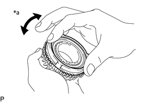
*a
Locks in both directions
Check for wear and damage.
Coat the 3rd gear cone with gear oil.
Turn the No. 3 synchronizer ring in both directions while pushing it against the 3rd gear cone and check that it locks in both directions.
If the No. 3 synchronizer ring does not lock, replace the No. 3 synchronizer ring.
-
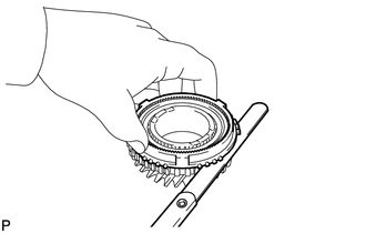
Using a feeler gauge, measure the clearance between the No. 3 synchronizer ring and gear spline end.
Standard clearance
0.78 to 1.62 mm (0.0308 to 0.0637 in.)
Minimum clearance
0.78 mm (0.0308 in.)
If the clearance is less than the minimum, replace the No. 3 synchronizer ring.
-
INSPECT NO. 2 TRANSMISSION HUB SLEEVE
-
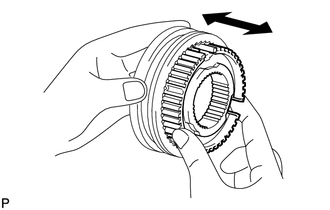
Check the sliding condition between the No. 2 transmission hub sleeve and No. 2 transmission clutch hub.
Check that the edges of the No. 2 transmission hub sleeve spline gear are not worn down.
-
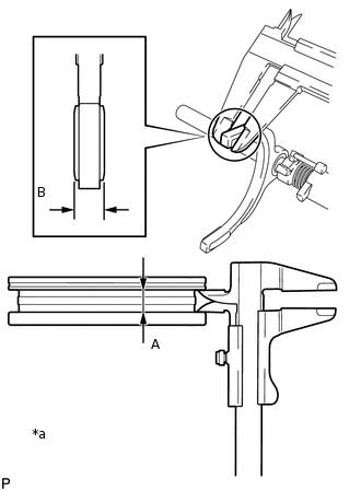
*a
Clearance = A - B
Using a vernier caliper, measure the width of the No. 2 transmission hub sleeve groove (A) and the thickness of the claw part on the No. 2 gear shift fork (B), and calculate the clearance.
Standard clearance (A - B)
0.1 to 0.5 mm (0.00394 to 0.01968 in.)
If the clearance is not as specified, replace the No. 2 transmission hub sleeve and No. 2 gear shift fork.
-
INSPECT NO. 3 TRANSMISSION HUB SLEEVE
-
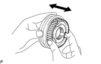
Check the sliding condition between the No. 3 transmission hub sleeve and No. 3 transmission clutch hub.
Check that the edges of the No. 3 transmission hub sleeve spline gear are not worn down.
-
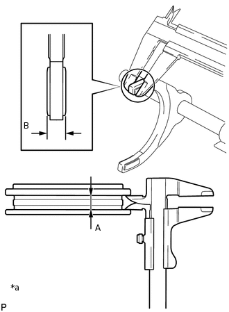
*a
Clearance = A - B
Using a vernier caliper, measure the width of the No. 3 transmission hub sleeve groove (A) and the thickness of the claw part on the No. 3 gear shift fork (B), and calculate the clearance.
Standard clearance (A - B)
0.1 to 0.5 mm (0.00394 to 0.01968 in.)
If the clearance is not as specified, replace the No. 3 transmission hub sleeve and No. 3 gear shift fork.
-