CLUTCH UNIT INSTALLATION
-
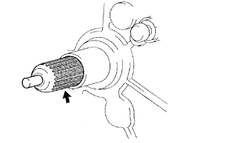
INSTALL INPUT SHAFT FRONT BEARING (for 1KD-FTV, 2KD-FTV)
-
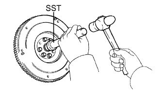
Using SST and a hammer, tap in a new bearing.
- SST
- 09304-12012
Tech Tips
After installing the bearing to the hub, make sure that it rotates smoothly.
-
Install 2 new bolts.
for 1KD-FTV: Click here
for 2KD-FTV: Click here
-
-
INSTALL INPUT SHAFT FRONT BEARING (for 1TR-FE, 2TR-FE)
-
Using SST and a hammer, tap in a new bearing.
- SST
- 09304-12012
Tech Tips
After installing the bearing to the hub, make sure that it rotates smoothly.
-
Install 2 new bolts.
for 1TR-FE: Click here
for 2TR-FE: Click here
-
-
INSTALL CLUTCH DISC ASSEMBLY
-
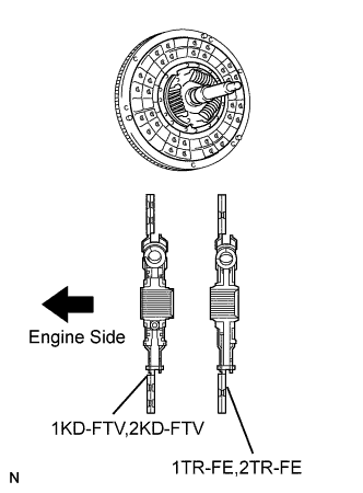
Insert SST into the clutch disc. Then insert the SST (together with the clutch disc) into the flywheel.
- SST
- 09301-00110
Note
Take care not to insert the clutch disc facing the wrong direction.
-
-
INSTALL CLUTCH COVER ASSEMBLY
-
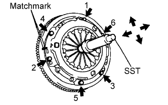
Align the matchmarks on the clutch cover and flywheel.
-
Tighten the 6 bolts as described below.
-
Determine the first bolt to be tightened by choosing the bolt closest to the knock pin.
-
Uniformly tighten the 6 bolts in diametrically opposite pairs relative to the position of the first bolt. Use the illustration as a reference.
- Torque:
- 19 N*m { 195 kgf*cm, 14 in.*lbf }
-
-
Lightly move SST up and down, and right and left.
- SST
- 09301-00110
-
Check that the disc is in the center, and then tighten the bolts.
-
-
INSPECT AND ADJUST CLUTCH COVER ASSEMBLY
-

Using a dial indicator with roller instrument, measure the diaphragm spring tip alignment.
Maximum misalignment 0.5 mm (0.020 in.)
-

If the alignment is not as specified, use SST to adjust the diaphragm spring tip alignment.
- SST
- 09333-00013
-
-
-
INSTALL RELEASE FORK SUPPORT
-
Install the release fork support to the manual transmission unit.
-
-
INSTALL RELEASE BEARING HUB CLIP
-
Install the release bearing hub clip to the release bearing.
-
-
INSTALL CLUTCH RELEASE FORK SUB-ASSEMBLY
-
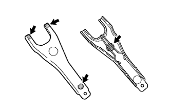
Apply Multemp 8158 Grease or equivalent to the following areas:
-
The contact surfaces of the release fork and release bearing hub.
-
The contact surfaces of the release fork and push rod.
-
The pivot points of the release fork.
Grease Multemp 8158 Grease or equivalent
-
-
Install the release fork to the release bearing.
-
-
INSTALL CLUTCH RELEASE BEARING ASSEMBLY
-
Apply clutch spline grease to the input shaft spline.
Grease Toyota Genuine Clutch Spline Grease or equivalent -
Install the release fork (with release bearing) to the manual transmission.
Note
After the installation, move the fork forward and backward to check that the release bearing slides smoothly.
-
-
INSTALL CLUTCH RELEASE FORK BOOT
-
INSTALL MANUAL TRANSMISSION UNIT ASSEMBLY
for G50/G55 manual transmission: Click here.
for R150F/R151F/R156F manual transmission: Click here.
for R150/R151/R156 manual transmission: Click here.