AIRBAG SYSTEM, Diagnostic DTC:B1660/43

| DTC Code | DTC Name |
|---|---|
| B1660/43 | Passenger Airbag ON/OFF Indicator Circuit Malfunction |
DESCRIPTION
The passenger airbag ON/OFF indicator circuit consists of the airbag sensor assembly and passenger airbag ON/OFF indicator.
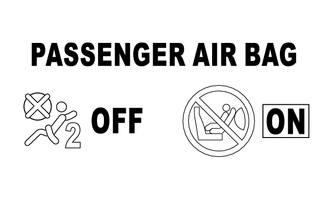
The passenger airbag ON/OFF indicator indicates the operation condition of the instrument panel passenger airbag assembly, front seat airbag and front seat outer belt assembly.
DTC B1660/43 is stored when a malfunction is detected in the passenger airbag ON/OFF indicator circuit.
| DTC Code | Detection Condition | Trouble Area |
|---|---|---|
| B1660/43 | One of the following conditions is met:
|
|
WIRING DIAGRAM
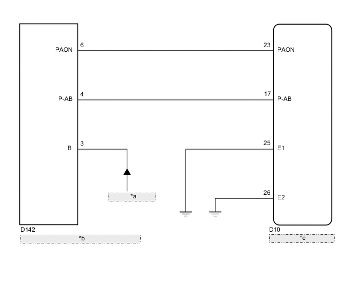
| *a | from ECU-IG No. 1 Fuse |
| *b | Upper Console Panel Sub-assembly (Passenger Airbag ON/OFF Indicator) |
| *c | Airbag Sensor Assembly |
CAUTION / NOTICE / HINT
Note
-
After turning the ignition switch off, waiting time may be required before disconnecting the cable from the negative (-) battery terminal. Therefore, make sure to read the disconnecting the cable from the negative (-) battery terminal notices before proceeding with work Click here.
-
When disconnecting the cable from the negative (-) battery terminal while performing repairs, some systems need to be initialized after the cable is reconnected Click here.
PROCEDURE
-
CHECK PASSENGER AIRBAG ON/OFF INDICATOR CONDITION
-
Turn the ignition switch to ON.
-
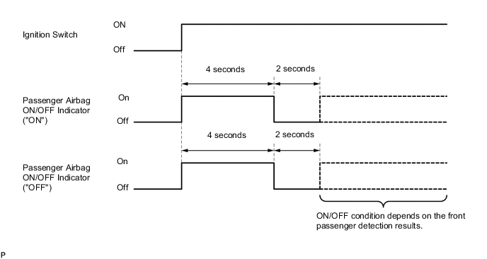
Check the passenger airbag ON/OFF indicator operation.
Tech Tips
Refer to the normal condition of the passenger airbag ON/OFF indicator Click here.
Result ON/OFF Indicator Illumination Proceed to One or both indicators are always on A Both indicators are always off B
B 
CHECK CONNECTION OF CONNECTORS Click here
A 
-
-
CHECK CONNECTION OF CONNECTORS
-
Turn the ignition switch off.
-
Disconnect the cable from the negative (-) battery terminal, and wait for at least 90 seconds.
-
Check that the connectors are properly connected to the airbag sensor assembly and upper console panel sub-assembly.
OK The connectors are properly connected.
NG 
CONNECT CONNECTORS PROPERLY
OK
-
-
CHECK CONNECTORS
-
Disconnect the connectors from the airbag sensor assembly and upper console panel sub-assembly.
-
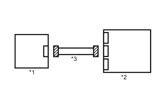
Text in Illustration *1 Upper Console Panel Sub-assembly *2 Airbag Sensor Assembly *3 Instrument Panel Wire Check that the connectors (on the airbag sensor assembly side and upper console panel sub-assembly side) are not damaged.
OK The connectors are not deformed or damaged.
NG
REPLACE INSTRUMENT PANEL WIRE
OK
-
-
CHECK PASSENGER AIRBAG ON/OFF INDICATOR
-
Connect the connector to the upper console panel sub-assembly.
-
Connect the cable to the negative (-) battery terminal, and wait for at least 2 seconds.
-
Turn the ignition switch to ON.
-
Check the passenger airbag ON/OFF indicator operation.
OK The passenger airbag ON/OFF indicator does not come on.
NG
CHECK INSTRUMENT PANEL WIRE Click here
OK
-
-
CHECK FOR DTC
-
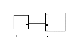
Text in Illustration *1 Upper Console Panel Sub-assembly *2 Airbag Sensor Assembly Connect the connector to the airbag sensor assembly.
-
Connect the cable to the negative (-) battery terminal, and wait for at least 2 seconds.
-
Turn the ignition switch to ON, and wait for at least 60 seconds.
-
Clear the DTCs Click here.
-
Turn the ignition switch off.
-
Turn the ignition switch to ON, and wait for at least 60 seconds.
-
Check for DTCs Click here.
OK DTC B1660/43 is not output. Tech Tips
Codes other than DTC B1660/43 may be output at this time, but they are not related to this check.
OK
USE SIMULATION METHOD TO CHECK Click here
NG
REPLACE AIRBAG SENSOR ASSEMBLY Click here
-
-
CHECK INSTRUMENT PANEL WIRE
-
Disconnect the connector from the upper console panel sub-assembly.
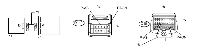
Text in Illustration *1 Upper Console Panel Sub-assembly *2 Airbag Sensor Assembly *3 Instrument Panel Wire *4 Connector C *5 Connector B *6 Service Wire *a Front view of wire harness connector
(to Upper Console Panel Sub-assembly)
*b Rear view of wire harness connector
(to Airbag Sensor Assembly)
-
Connect the cable to the negative (-) battery terminal, and wait for at least 2 seconds.
-
Turn the ignition switch to ON.
-
Measure the voltage according to the value(s) in the table below.
Standard Voltage Tester Connection Switch Condition Specified Condition D142-6 (PAON) - Body ground Ignition switch ON Below 1 V D142-4 (P-AB) - Body ground Ignition switch ON Below 1 V -
Turn the ignition switch off.
-
Disconnect the cable from the negative (-) battery terminal, and wait for at least 90 seconds.
-
Using a service wire, connect terminals 23 (PAON) and 17 (P-AB) of connector B.
Note
Do not forcibly insert the service wire into the terminals of the connector when connecting a service wire.
-
Measure the resistance according to the value(s) in the table below.
Standard Resistance Tester Connection Condition Specified Condition D142-6 (PAON) - D142-4 (P-AB) Always Below 1 Ω -
Disconnect the service wire from connector B.
-
Measure the resistance according to the value(s) in the table below.
Standard Resistance Tester Connection Condition Specified Condition D142-6 (PAON) - D142-4 (P-AB) Always 1 MΩ or higher D142-6 (PAON) - Body ground Always 1 MΩ or higher D142-4 (P-AB) - Body ground Always 1 MΩ or higher
OK
REPLACE UPPER CONSOLE PANEL SUB-ASSEMBLY Click here
NG
REPLACE INSTRUMENT PANEL WIRE
-
-
CHECK CONNECTION OF CONNECTORS
-
Turn the ignition switch off.
-
Disconnect the cable from the negative (-) battery terminal, and wait for at least 90 seconds.
-
Check that the connectors are properly connected to the airbag sensor assembly and upper console panel sub-assembly.
OK The connectors are properly connected.
NG
CONNECT CONNECTORS PROPERLY
OK
-
-
CHECK CONNECTORS
-
Text in Illustration *1 Upper Console Panel Sub-assembly *2 Airbag Sensor Assembly *3 Instrument Panel Wire Disconnect the connectors from the airbag sensor assembly and upper console panel sub-assembly.
-
Check that the connectors (on the airbag sensor assembly side and upper console panel sub-assembly side) are not damaged.
OK The connectors are not deformed or damaged.
NG
REPLACE INSTRUMENT PANEL WIRE
OK
-
-
CHECK INSTRUMENT PANEL WIRE
-
Connect the cable to the negative (-) battery terminal, and wait for at least 2 seconds.
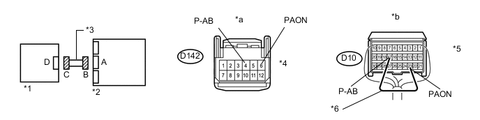
Text in Illustration *1 Upper Console Panel Sub-assembly *2 Airbag Sensor Assembly *3 Instrument Panel Wire *4 Connector C *5 Connector B *6 Service Wire *a Front view of wire harness connector
(to Upper Console Panel Sub-assembly)
*b Rear view of wire harness connector
(to Airbag Sensor Assembly)
-
Turn the ignition switch to ON.
-
Measure the voltage according to the value(s) in the table below.
Standard Voltage Tester Connection Switch Condition Specified Condition D142-6 (PAON) - Body ground Ignition switch ON Below 1 V D142-4 (P-AB) - Body ground Ignition switch ON Below 1 V -
Turn the ignition switch off.
-
Disconnect the cable from the negative (-) battery terminal, and wait for at least 90 seconds.
-
Using a service wire, connect terminals 23 (PAON) and 17 (P-AB) of connector B.
Note
Do not forcibly insert the service wire into the terminals of the connector when connecting a service wire.
-
Measure the resistance according to the value(s) in the table below.
Standard Resistance Tester Connection Condition Specified Condition D142-6 (PAON) - D142-4 (P-AB) Always Below 1 Ω -
Disconnect the service wire from connector B.
-
Measure the resistance according to the value(s) in the table below.
Standard Resistance Tester Connection Condition Specified Condition D142-6 (PAON) - D142-4 (P-AB) Always 1 MΩ or higher D142-6 (PAON) - Body ground Always 1 MΩ or higher D142-4 (P-AB) - Body ground Always 1 MΩ or higher
NG
REPLACE INSTRUMENT PANEL WIRE
OK
-
-
CHECK PASSENGER AIRBAG ON/OFF INDICATOR (SOURCE VOLTAGE)
-
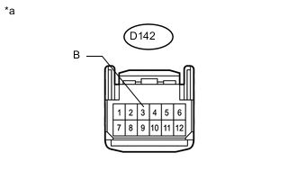
Text in Illustration *a Front view of wire harness connector
(to Upper Console Panel Sub-assembly)
Connect the connectors to the airbag sensor assembly.
-
Connect the cable to the negative (-) battery terminal, and wait for at least 2 seconds.
-
Turn the ignition switch to ON.
-
Measure the voltage according to the value(s) in the table below.
Standard Voltage Tester Connection Switch Condition Specified Condition D142-3 (B) - Body ground Ignition switch ON 11 to 14 V
NG
REPAIR OR REPLACE HARNESS AND CONNECTOR
OK
-
-
CHECK PASSENGER AIRBAG ON/OFF INDICATOR
-
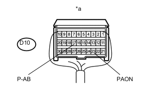
Text in Illustration *a Rear view of wire harness connector
(to Airbag Sensor Assembly)
Turn the ignition switch off.
-
Disconnect the cable from the negative (-) battery terminal, and wait for at least 90 seconds.
-
Connect the connector to the upper console panel sub-assembly.
-
Disconnect the connectors from the airbag sensor assembly.
-
Using a service wire, connect terminal 23 (PAON) and body ground.
-
Using a service wire, connect terminal 17 (P-AB) and body ground.
-
Connect the cable to the negative (-) battery terminal, and wait for at least 2 seconds.
-
Turn the ignition switch to ON.
-
Check the indicator according to the table below.
OK Connection Switch Condition Passenger Airbag ON/OFF Indicator D10-23 (PAON) - Body ground Ignition switch ON "ON" comes on D10-17 (P-AB) - Body ground Ignition switch ON "OFF" comes on
NG
REPLACE UPPER CONSOLE PANEL SUB-ASSEMBLY Click here
OK
-
-
CHECK FOR DTC
-
Text in Illustration *1 Upper Console Panel Sub-assembly *2 Airbag Sensor Assembly Turn the ignition switch off.
-
Disconnect the cable from the negative (-) battery terminal, and wait for at least 90 seconds.
-
Connect the connectors to the airbag sensor assembly.
-
Connect the cable to the negative (-) battery terminal and wait for at least 2 seconds.
-
Turn the ignition switch to ON, and wait for at least 60 seconds.
-
Clear the DTCs Click here.
-
Turn the ignition switch off.
-
Turn the ignition switch to ON, and wait for at least 60 seconds.
-
Check for DTCs Click here.
OK DTC B1660/43 is not output. Tech Tips
Codes other than DTC B1660/43 may be output at this time, but they are not related to this check.
OK
USE SIMULATION METHOD TO CHECK Click here
NG
REPLACE AIRBAG SENSOR ASSEMBLY Click here
-