CYLINDER HEAD REPLACEMENT

PROCEDURE
-
REPLACE NO. 2 INTAKE VALVE GUIDE BUSH
-
Place the cylinder block on wooden blocks with the combustion chamber side facing upward.
-
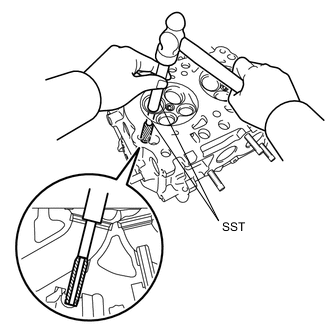
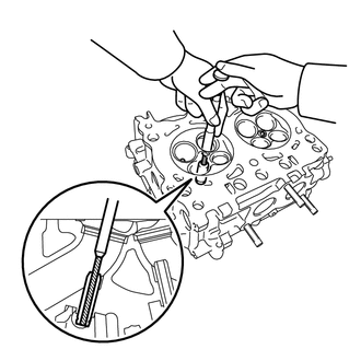
Using SST and a hammer, tap out the No. 2 intake valve guide bush.
- SST
- 09201-10000 ( 09201-01050 )
- 09950-70010 ( 09951-07100 )
Note
-
Place wooden blocks wrapped in a cloth under the cylinder head and stabilize the cylinder head during servicing.
-
Use special care not to damage the cylinder head.
-
Before installing the No. 2 intake valve guide bush, make sure that neither scratches nor damages exist on the inner surface of cylinder head valve guide bush holes.
-
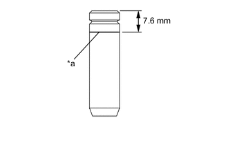
Text in Illustration *a Reference line Draw a reference line 7.6 mm (0.299 in.) below from the top face on a new No. 2 intake valve guide bush using a marker.
Tech Tips
Reference line is used as a guide when tapping-in the No. 2 intake valve guide bush.
-
Place the cylinder block on wooden blocks with the combustion chamber side facing downward.
-
Apply enough engine oil to the No. 2 intake valve guide bush, and set it on the cylinder head.
-
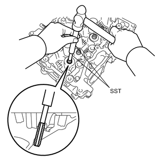
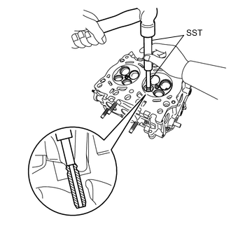
Using SST and a hammer, tap in the No. 2 intake valve guide bush to the reference line.
- SST
- 09201-10000 ( 09201-01050 )
- 09950-70010 ( 09951-07100 )
Note
-
Place wooden blocks wrapped in a cloth under the cylinder head and stabilize the cylinder head during servicing.
-
Use special care not to damage the cylinder head.
-
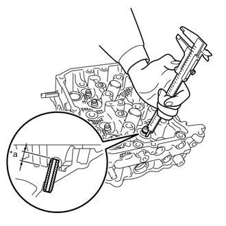
Text in Illustration *a Protrusion height While measuring the No. 2 intake valve guide bush protrusion amount using a vernier caliper, tap in the No. 2 intake valve guide bush so that its height is within the standard.
Standard protrusion height 11.4 to 11.8 mm (0.449 to 0.466 in.) Note
-
Place wooden blocks wrapped in a cloth under the cylinder head and stabilize the cylinder head during servicing.
-
Use special care not to damage the cylinder head.
Tech Tips
Use multiple small repetitions of tap-in and measurement in order not to excessively tap in the No. 2 intake valve guide bush.
-
-
Place the cylinder block on wooden blocks with the combustion chamber side facing upward.
Note
-
Place wooden blocks wrapped in a cloth under the cylinder head and stabilize the cylinder head during servicing.
-
Use special care not to damage the cylinder head.
-
-
Using a reamer, ream the No. 2 intake valve guide bush to obtain the standard clearance between the No. 2 intake valve guide bush and valve stem.
Standard inside diameter 5.500 to 5.512 mm (0.21654 to 0.21701 in.) at 20°C (68°F) Note
While gradually widening the reamer diameter, ream the No. 2 intake valve guide bush uniformly so that the oil clearance is within the standard.
Tech Tips
-
Apply engine oil to the reamer when reaming.
-
If the inner surface of No. 2 intake valve guide bush is damaged, slightly grind the edge of the reamer with 400-grit sandpaper.
-
If the inner surface of No. 2 intake valve guide bush becomes lustrous and the reamer does not chip, use a new reamer or correct the reamer.
-
-
After reaming, remove chips and clean the No. 2 intake valve guide bush.
-
Measure the inside diameter of the No. 2 intake valve guide bush and confirm the oil clearance.
-
Check the contact condition between the valve and valve seat.
-
-
REPLACE NO. 2 EXHAUST VALVE GUIDE BUSH
-
Place the cylinder block on wooden blocks with the combustion chamber side facing upward.
-
Using SST and a hammer, tap out the No. 2 exhaust valve guide bush.
- SST
- 09201-10000 ( 09201-01050 )
- 09950-70010 ( 09951-07100 )
Note
-
Place wooden blocks wrapped in a cloth under the cylinder head and stabilize the cylinder head during servicing.
-
Use special care not to damage the cylinder head.
-
Before installing the No. 2 exhaust valve guide bush, make sure that neither scratches nor damages exist on the inner surface of cylinder head valve guide bush holes.
-
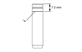
Text in Illustration *a Reference line Draw a reference line 7.0 mm (0.276 in.) below from the top face on a new No. 2 exhaust valve guide bush using a marker.
Tech Tips
Reference line is used as a guide when tapping-in the No. 2 exhaust valve guide bush.
-
Place the cylinder block on wooden blocks with the combustion chamber side facing downward.
-
Apply enough engine oil to the No. 2 exhaust valve guide bush, and set it on the cylinder head.
-
Using SST and a hammer, tap in the No. 2 exhaust valve guide bush to the reference line.
- SST
- 09201-10000 ( 09201-01050 )
- 09950-70010 ( 09951-07100 )
Note
-
Place wooden blocks wrapped in a cloth under the cylinder head and stabilize the cylinder head during servicing.
-
Use special care not to damage the cylinder head.
-
Text in Illustration *a Protrusion height While measuring the No. 2 exhaust valve guide bush protrusion amount using a vernier caliper, tap in the No. 2 exhaust valve guide bush so that its height is within the standard.
Standard protrusion height 11.4 to 11.8 mm (0.449 to 0.466 in.) Note
-
Place wooden blocks wrapped in a cloth under the cylinder head and stabilize the cylinder head during servicing.
-
Use special care not to damage the cylinder head.
Tech Tips
Use multiple small repetitions of tap-in and measurement in order not to excessively tap in the No. 2 exhaust valve guide bush.
-
-
Place the cylinder block on wooden blocks with the combustion chamber side facing upward.
Note
-
Place wooden blocks wrapped in a cloth under the cylinder head and stabilize the cylinder head during servicing.
-
Use special care not to damage the cylinder head.
-
-
Using a reamer, ream the No. 2 exhaust valve guide bush to obtain the standard clearance between the No. 2 exhaust valve guide bush and valve stem.
Standard inside diameter 5.500 to 5.512 mm (0.21654 to 0.21701 in.) at 20°C (68°F) Note
While gradually widening the reamer diameter, ream the No. 2 exhaust valve guide bush uniformly so that the oil clearance is within the standard.
Tech Tips
-
Apply engine oil to the reamer when reaming.
-
If the inner surface of No. 2 exhaust valve guide bush is damaged, slightly grind the edge of the reamer with 400-grit sandpaper.
-
If the inner surface of No. 2 exhaust valve guide bush becomes lustrous and the reamer does not chip, use a new reamer or correct the reamer.
-
-
After reaming, remove chips and clean the No. 2 exhaust valve guide bush.
-
Measure the inside diameter of the No. 2 exhaust valve guide bush and confirm the oil clearance.
-
Check the contact condition between the valve and valve seat.
-