AIR CONDITIONING SYSTEM(for Manual Air Conditioning System) SYSTEM DESCRIPTION
-
GENERAL
The air conditioning system has the following controls.
Control Outline Blower Control Controls the blower motor in accordance with the airflow volume that has been calculated by neural network control based on input signals from various sensors. Air Outlet Control Automatically switches the air outlets in accordance with the outlet mode that has been calculated by neural network control. In accordance with the engine coolant temperature, ambient air temperature, amount of sunlight, required blower, outlet temperature and vehicle speed conditions, this control automatically switches the blower outlet to foot/defroster mode to prevent the windows from becoming fogged up when the ambient air temperature is low. Air Inlet Control Automatically controls the air inlet control damper to help achieve the calculated outlet air temperature that is required. Drives the air inlet control servo motor according to the operation of the air inlet control switch and moves the dampers to the fresh or recirculation position. Variable Capacity Compressor Control Controls the compressor with pulley assembly to turn it on or off and adjust the discharge capacity based on the signals from various sensors. Defroster Control Defroster control logic is used to improve defroster performance. PTC Heater Control*1 When the engine is running, and the blower motor with fan sub-assembly is turned on, the air conditioning amplifier assembly turns on the quick heater assembly if the conditions listed below are met.
-
Engine coolant temperature is below specified temperature.
-
Outside temperature is below specified temperature.
-
Tentative air mix damper opening angle is above the specified value (MAX HOT).
Diagnosis A Diagnostic Trouble Code (DTC) is stored in memory when the air conditioning amplifier assembly detects a problem with the air conditioning system. *1: w/ PTC Heater
-
-
MODE POSITION AND DAMPER OPERATION
Mode Position and Damper Operation
Figure 1. w/ Headlight Cleaner System
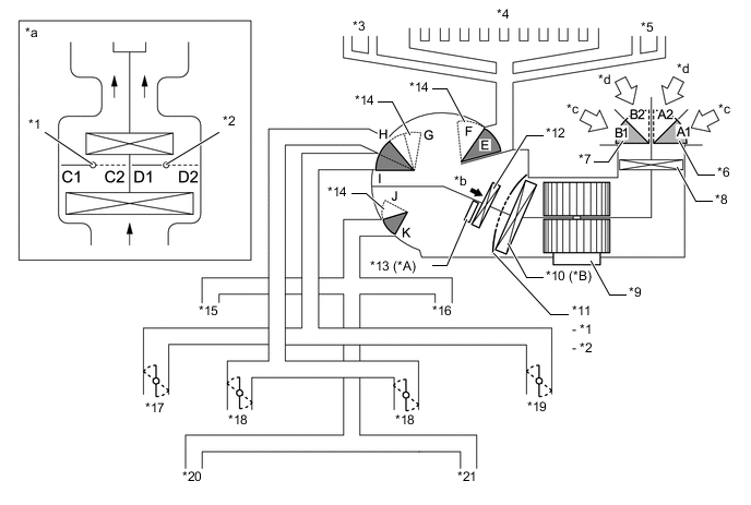
*A w/ PTC Heater *B w/ Cooler System *1 No. 1 Air Conditioning Radiator Damper Servo Sub-assembly (Upper Air Mix) *2 No. 1 Air Conditioning Radiator Damper Servo Sub-assembly (Lower Air Mix) *3 Side Defroster LH *4 Front Defroster *5 Side Defroster RH *6 No. 1 Blower Damper Servo Sub-assembly (Fresh/Recirculation) (Lower Side) *7 No. 1 Blower Damper Servo Sub-assembly (Fresh/Recirculation) (Upper Side) *8 Clean Air Filter *9 Blower Motor with Fan Sub-assembly *10 No. 1 Cooler Evaporator Sub-assembly *11 No. 1 Air Conditioning Radiator Damper Servo Sub-assembly (Air Mix Control Damper) *12 Heater Radiator Unit Sub-assembly *13 Quick Heater Assembly *14 No. 2 Air Conditioning Radiator Damper Servo Sub-assembly (Mode Switching) *15 Front Footwell Register LH *16 Front Footwell Register RH *17 Side Register LH *18 Center Register *19 Side Register RH *20 Rear Footwell Register LH *21 Rear Footwell Register RH - - *a Illustration Image View from [A] *b [A] View *c Recirculated Air *d Fresh Air Functions of Main Dampers Control Damper Operation Position Damper Position Operation Air Inlet Control Damper FRESH A1, B1 Allows fresh air to enter. RECIRCULATION A2, B2 Causes internal air to recirculate. Air Mix Control Damper HI - LO C1 - C2 Varies the mixture ratio of the fresh air and the recirculation air in order to regulate the temperature continuously from HI to LO. D2 - D1 Varies the mixture ratio of the fresh air and the recirculation air in order to regulate the temperature continuously from HI to LO. Air Outlet Control Damper DEF

F, H, K Defrosts the windshield through the center defroster, side defrosters and side registers. FOOT/DEF

F, H, J to K Defrosts the windshield through the center defroster, side defrosters and side registers, while air is also blown out from the front and rear footwell register ducts. FOOT

E, (E to F), H, J Air blows out of the front and rear footwell register ducts and side registers. In addition, air blows out slightly from the center defroster and side defrosters. B/L

E, G to I, J to K Air blows out of the center registers, side registers and front and rear footwell register ducts. FACE

E, G, K Air blows out of the center registers and side registers. Figure 2. w/o Headlight Cleaner System
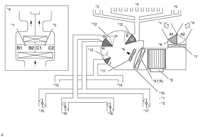
*A w/ Cooler System - - *1 No. 1 Air Conditioning Radiator Damper Servo Sub-assembly (Upper Air Mix) *2 No. 1 Air Conditioning Radiator Damper Servo Sub-assembly (Lower Air Mix) *3 Side Defroster LH *4 Front Defroster *5 Side Defroster RH *6 No. 1 Blower Damper Servo Sub-assembly (Fresh/Recirculation) *7 Clean Air Filter *8 Blower Motor with Fan Sub-assembly *9 No. 1 Cooler Evaporator Sub-assembly *10 No. 1 Air Conditioning Radiator Damper Servo Sub-assembly (Air Mix Control Damper) *11 Heater Radiator Unit Sub-assembly *12 No. 2 Air Conditioning Radiator Damper Servo Sub-assembly (Mode Switching) *13 Front Footwell Register LH *14 Front Footwell Register RH *15 Side Register LH *16 Center Register *17 Side Register RH - - *a Illustration Image View from [A] *b [A] View *c Recirculated Air *d Fresh Air Functions of Main Dampers Control Damper Operation Position Damper Position Operation Air Inlet Control Damper FRESH A1 Allows fresh air to enter. RECIRCULATION A2 Causes internal air to recirculate. Air Mix Control Damper HI - LO B1 - B2 Varies the mixture ratio of cool air and hot air in order to regulate the temperature continuously from HI to LO. C2 - C1 Varies the mixture ratio of cool air and hot air in order to regulate the temperature continuously from HI to LO. Air Outlet Control Damper DEF
E, G, J Defrosts the windshield through the center defroster, side defrosters and side registers. FOOT/DEF
E, G, I to J Defrosts the windshield through the center defroster, side defrosters and side registers, while air is also blown out from the front footwell register ducts. FOOT
D, (D to E), G, I Air blows out of the front footwell register ducts and side registers. In addition, air blows out slightly from the center defroster and side defrosters. B/L
D, F to H, I to J Air blows out of the center registers, side registers and front footwell register ducts. FACE
D, F, J Air blows out of the center registers and side registers. -
AIR OUTLETS AND AIRFLOW VOLUME
The size of each circle ○ indicates the ratio of airflow volume.
-
Air Outlets and Airflow Volume.
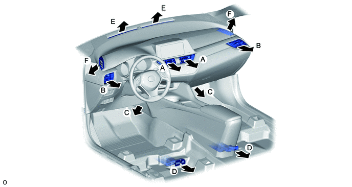
Mode FACE FOOT DEF Center Side Front Rear* Center Side A B C D E F FACE


B/L


FOOT
FOOT/DEF
DEF
-
*: w/ Headlight Cleaner System
-
-
-
COMPRESSOR (w/ Cooler System)
-
General:
-
The compressor is a continuously variable capacity type in which its capacity can be varied in accordance with the cooling load of the air conditioning system.
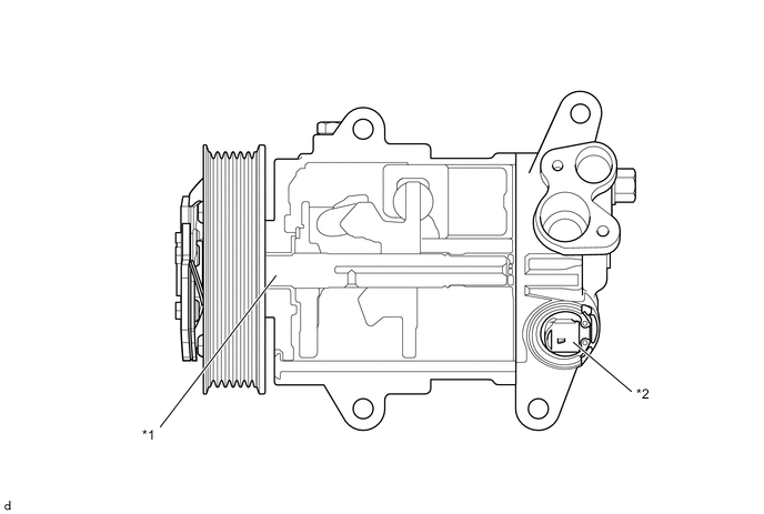
*1 Shaft *2 Solenoid Control Valve
-
-
Solenoid Valve Operation:
-
The crank chamber is connected to the suction passage. A solenoid valve is provided between the suction passage (low pressure) and the discharge passage (high pressure).
-
The solenoid valve operates under duty cycle control in accordance with the signals from the air conditioning amplifier assembly.
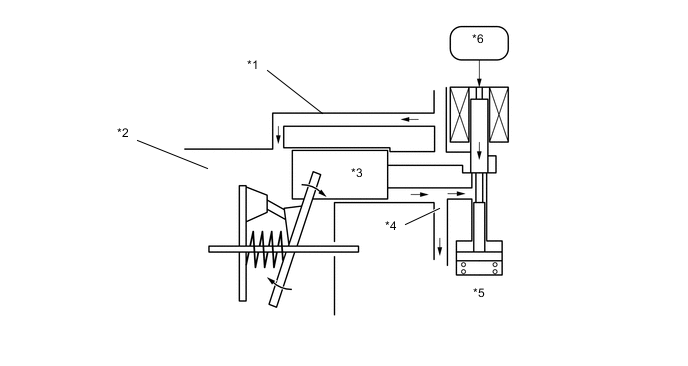
*1 Suction Passage *2 Crank Chamber *3 Piston *4 Discharge Passage *5 Solenoid Control Valve *6 Air Conditioning Amplifier Assembly -
When the solenoid valve closes (solenoid coil is energized), a difference in pressure is created and the pressure in the crank chamber decreases. Then, the pressure that is applied to the right side of the piston becomes greater than the pressure that is applied to the left side of the piston. This compresses the spring and tilts the swash plate. As a result, the piston stroke increases and the discharge capacity also increases.
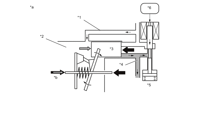
*1 Suction Passage *2 Crank Chamber *3 Piston *4 Discharge Passage *5 Solenoid Control Valve *6 Air Conditioning Amplifier Assembly *a Piston Stroke: Large *b Crank Chamber Pressure + Spring Force -
When the solenoid valve opens (solenoid coil is not energized), the difference in pressure disappears. Then, the pressure that is applied to the left side of the piston becomes the same as the pressure that is applied to the right side of the piston. Thus, the spring elongates and eliminates the tilt of the swash plate. As a result, there is no piston stroke, and the discharge capacity is reduced.
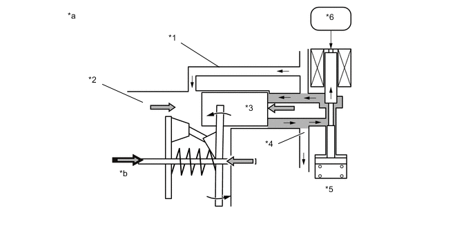
*1 Suction Passage *2 Crank Chamber *3 Piston *4 Discharge Passage *5 Solenoid Control Valve *6 Air Conditioning Amplifier Assembly *a Piston Stroke: Small *b Crank Chamber Pressure + Spring Force
-
-
CS Valve Operation:
-
The CS valve consists of passage A and passage B. If the vehicle is left parked for a long period, refrigerant may accumulate in the crank chamber due to the heat capacity difference.
-
The solenoid control valve is controlled by the air conditioning amplifier assembly. While the compressor is operating, the solenoid control valve pushes down the CS valve rod and opens passage A.
-
Under the above condition, only if the refrigerant accumulates in the crank chamber, the crank chamber pressure will become high. As a result, the bellows will contract because of the pressure difference with its internal pressure (vacuum), and opens passage B.
-
This causes the accumulated refrigerant to be drawn in via passage A and passage B, clearing the accumulated refrigerant earlier and ensuring a more immediate cooling effect.
-
-
-
NO. 1 COOLER THERMISTOR (EVAPORATOR TEMPERATURE SENSOR) (w/ Cooler System)
The No. 1 cooler thermistor (evaporator temperature sensor) detects the temperature of the cool air immediately after the evaporator in the form of resistance changes, and outputs it to the air conditioning amplifier assembly.
-
BLOWER MOTOR WITH FAN SUB-ASSEMBLY
The blower motor is controlled using duty control performed via the blower resistor from the air conditioning amplifier assembly.
-
BLOWER RESISTOR
The blower resistor controls the blower motor with fan sub-assembly based on changes in the signal sent by the air conditioning amplifier assembly.
-
SERVO MOTOR
Servo motor, uses a step motor type. The motor inside of four coils have always added the battery voltage. An air conditioning amplifier assembly is as many times as necessary until the position of the target, move the voltage of each of the coil to the position of the target repeat the ON and OFF in order.
-
QUICK HEATER ASSEMBLY (w/ PTC Heater)
-
General
-
The quick heater assembly is located above the heater core in the air conditioning radiator assembly.
-
The quick heater assembly consists of a PTC element, aluminum fins, and brass plates. When current is applied to the PTC element, it generates heat to warm the air that passes through the unit.
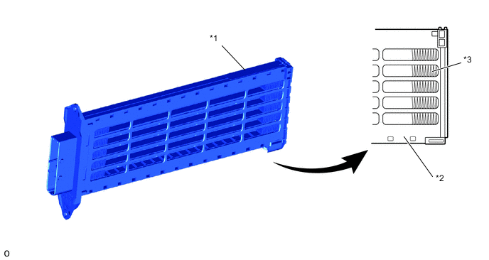
*1 Quick Heater Assembly *2 Heat Resistant Resin Plate *3 Fin - -
-
-
Quick Heater Assembly Operating Conditions
-
The quick heater assembly is turned on and off by the air conditioning amplifier assembly in accordance with the engine coolant temperature, ambient temperature, temperature setting, and electrical load (generator power ratio).
-
-
-
THERMISTOR ASSEMBLY
The thermistor assembly detects the outside temperature based on changes in the resistance of its built-in thermistor and sends a signal to the combination meter assembly and via CAN communication, it sends the outside temperature information to air conditioning amplifier assembly.
-
AIR CONDITIONER PRESSURE SENSOR (w/ Cooler System)
The air conditioner pressure sensor detects the refrigerant pressure and outputs it to the air conditioning amplifier assembly in the form of voltage changes.