VEHICLE STABILITY CONTROL SYSTEM, Diagnostic DTC:C1249
| DTC Code | DTC Name |
|---|---|
| C1249 | Open in Stop Light Switch Circuit |
DESCRIPTION
The skid control ECU (brake actuator assembly) receives stop light switch signals and uses them to determine whether or not the brakes are applied. DTCs may be stored if either of the following occurs:
Stop light switch stuck on malfunction.
The accelerator and brake pedals are depressed simultaneously.*
*: The skid control ECU (brake actuator assembly) may store this DTC upon judging that a stuck on malfunction has occurred when the accelerator pedal and brake pedal are depressed simultaneously. However, this does not indicate a malfunction.
DTC No. |
Detection Item |
DTC Detection Condition |
Trouble Area |
Note |
|---|---|---|---|---|
C1249 |
Open in Stop Light Switch Circuit |
The vehicle speed is 10 km/h (6 mph) or more, the accelerator pedal is depressed, the master cylinder pressure is 0.5 MPa (5.09 kgf/cm2, 72 psi) or less, and the stop light switch is on for 60 seconds or more. |
|
Tire pressure warning light (w/ tire pressure warning system) is off. |
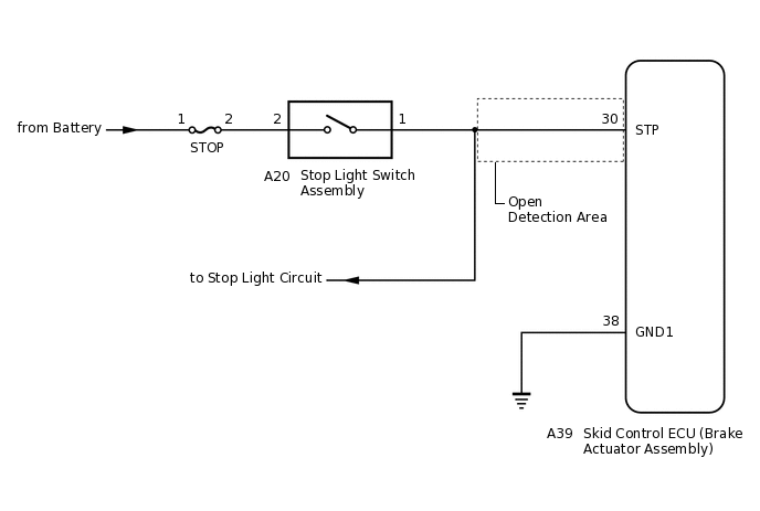
WIRING DIAGRAM
CAUTION / NOTICE / HINT
When replacing the skid control ECU (brake actuator assembly), perform system variant learning and acceleration sensor zero point calibration.
Inspect the fuses for circuits related to this system before performing the following procedure.
PROCEDURE
CHECK ACCELERATOR PEDAL AND BRAKE PEDAL OPERATION
Interview the customer to check if the pedals were depressed simultaneously while driving or braking.
OK
The pedals were not depressed simultaneously.
Tip:The skid control ECU (brake actuator assembly) may store this DTC upon judging that a stuck on malfunction has occurred when the accelerator pedal and brake pedal are depressed simultaneously.
If the pedals were depressed simultaneously, clear the DTC because it is not a malfunction.
Result
Proceed to
OK
NG
NG CLEAR DTC
CHECK STOP LIGHT OPERATION
Check that the stop lights come on when the brake pedal is depressed, and go off when the brake pedal is released.
OK
Condition
Illumination Condition
Brake pedal depressed.
On
Brake pedal released.
Off
Result
Proceed to
OK
NG
NG INSPECT STOP LIGHT SWITCH ASSEMBLYClick here
READ VALUE USING GTS (STOP LIGHT SWITCH ASSEMBLY)
Connect the GTS to the DLC3.
Turn the ignition switch to ON.
Select the Data List using the GTS.
Chassis > ABS/VSC/TRC > Data List
Tester Display
Measurement Item
Range
Normal Condition
Diagnostic Note
Stop Light SW
Stop light switch
ON or OFF
ON: Brake pedal depressed
OFF: Brake pedal released
-
Chassis > ABS/VSC/TRC > Data List
Tester Display
Stop Light SW
Check that the stop light switch display observed on the GTS changes according to brake pedal operation.
OK
The GTS displays ON or OFF according to brake pedal operation.
Result
Proceed to
OK
NG
NG CHECK HARNESS AND CONNECTOR (STP TERMINAL)Click here
RECONFIRM DTC
Turn the ignition switch off.
Clear the DTCs.
Chassis > ABS/VSC/TRC > Clear DTCs
Turn the ignition switch off.
Start the engine.
Drive the vehicle and depress the brake pedal several times to test the stop light circuit.
Check if the same DTC is output.
Chassis > ABS/VSC/TRC > Trouble Codes
Result
Result
Proceed to
DTC C1249 is not output.
A
DTC C1249 is output.
B
Tip:If troubleshooting has been carried out according to Problem Symptoms Table, refer back to the table and proceed to the next step before replacing parts.
CHECK HARNESS AND CONNECTOR (STP TERMINAL)
-
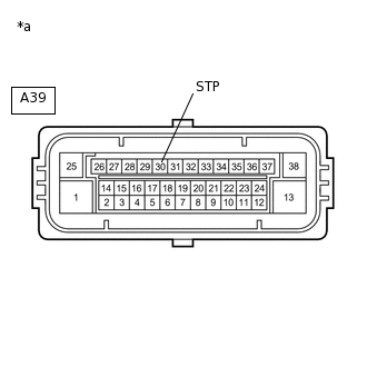
*a
Front view of wire harness connector
(to Skid Control ECU (Brake Actuator Assembly))
Turn the ignition switch off.
Make sure that there is no looseness at the locking part and the connecting part of the connector.
Disconnect the A39 skid control ECU (brake actuator assembly) connector.
Measure the voltage according to the value(s) in the table below.
Standard Voltage
Tester Connection
Condition
Specified Condition
A39-30 (STP) - Body ground
Stop light switch ON (Brake pedal depressed)
11 to 14 V*
A39-30 (STP) - Body ground
Stop light switch OFF (Brake pedal released)
Below 1.5 V
Tip:*: The standard voltage value varies depending on the +BS terminal voltage value. The standard voltage is 85% of the +BS terminal voltage.
Result
Proceed to
OK
NG
Tip:If troubleshooting has been carried out according to Problem Symptoms Table, refer back to the table and proceed to the next step before replacing parts.
NG REPAIR OR REPLACE HARNESS OR CONNECTOR (STP CIRCUIT)
-
INSPECT STOP LIGHT SWITCH ASSEMBLY
Check the stop light switch assembly.
OK
The stop light switch assembly is normal.
Result
Result
Proceed to
OK (w/ Stop Light Control Relay)
A
OK (w/o Stop Light Control Relay)
B
NG
C
B CHECK HARNESS AND CONNECTOR (STP TERMINAL)Click here
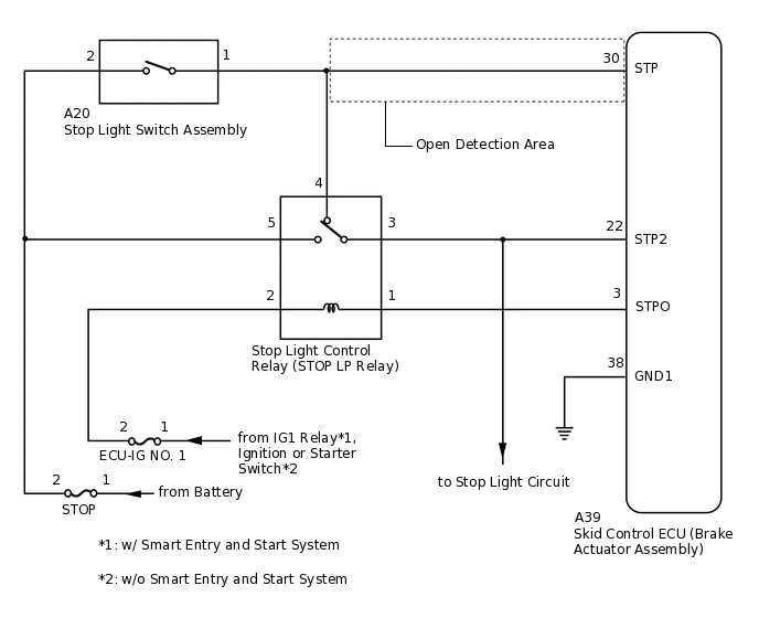
CHECK HARNESS AND CONNECTOR (SWITCH INPUT TERMINAL)
-
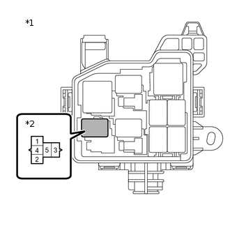
*1
No. 2 Engine Room Relay Block
*2
Stop Light Control Relay (STOP LP Relay)
Remove the stop light control relay (STOP LP relay).
Reconnect the A20 stop light switch assembly connector.
Measure the voltage according to the value(s) in the table below.
Standard Voltage
Tester Connection
Condition
Specified Condition
Stop light control relay (STOP LP relay) terminal 4 - Body ground
Stop light switch ON (Brake pedal depressed)
11 to 14 V*
Stop light control relay (STOP LP relay) terminal 4 - Body ground
Stop light switch OFF (Brake pedal released)
Below 1.5 V
Tip:*: The standard voltage value varies depending on the +BS terminal voltage value. The standard voltage is 85% of the +BS terminal voltage.
Result
Proceed to
OK
NG
NG REPAIR OR REPLACE HARNESS OR CONNECTOR (SWITCH INPUT CIRCUIT)
-
INSPECT STOP LIGHT CONTROL RELAY (STOP LP RELAY)
-
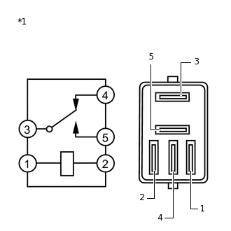
*1
Stop Light Control Relay (STOP LP Relay)
Measure the resistance according to the value(s) in the table below.
Standard Resistance
Tester Connection
Condition
Specified Condition
3 - 4
Voltage is not applied between terminals 1 and 2
Below 1 Ω
3 - 4
Voltage is applied between terminals 1 and 2
10 kΩ or higher
Result
Proceed to
OK
NG
NG REPLACE STOP LIGHT CONTROL RELAY (STOP LP RELAY)
-
CHECK HARNESS AND CONNECTOR (STP TERMINAL)
-
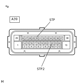
*a
Front view of wire harness connector
(to Skid Control ECU (Brake Actuator Assembly))
Install the stop light control relay (STOP LP relay).
Make sure that there is no looseness at the locking part and the connecting part of the connector.
Disconnect the A39 skid control ECU (brake actuator assembly) connector.
Measure the voltage according to the value(s) in the table below.
Standard Voltage
Tester Connection
Condition
Specified Condition
A39-30 (STP) - Body ground
Stop light switch ON (Brake pedal depressed)
11 to 14 V*
A39-30 (STP) - Body ground
Stop light switch OFF (Brake pedal released)
Below 1.5 V
A39-22 (STP2) - Body ground
Stop light switch ON (Brake pedal depressed)
11 to 14 V*
A39-22 (STP2) - Body ground
Stop light switch OFF (Brake pedal released)
Below 1.5 V
Tip:*: The standard voltage value varies depending on the +BS terminal voltage value. The standard voltage is 85% of the +BS terminal voltage.
Result
Proceed to
OK
NG
NG REPAIR OR REPLACE HARNESS OR CONNECTOR (STP CIRCUIT)
-
RECONFIRM DTC
Reconnect the A39 skid control ECU (brake actuator assembly) connector.
Clear the DTCs.
Chassis > ABS/VSC/TRC > Clear DTCs
Turn the ignition switch off.
Start the engine.
Drive the vehicle and depress the brake pedal several times to test the stop light circuit.
Check if the same DTC is output.
Chassis > ABS/VSC/TRC > Trouble Codes
Result
Result
Proceed to
DTC C1249 is not output.
A
DTC C1249 is output.
B
Tip:If the lighting system is normal but the DTC is still output, replace the skid control ECU (brake actuator assembly).
If troubleshooting has been carried out according to Problem Symptoms Table, refer back to the table and proceed to the next step before replacing parts.
CHECK HARNESS AND CONNECTOR (STP TERMINAL)
-
*a
Front view of wire harness connector
(to Skid Control ECU (Brake Actuator Assembly))
Reconnect the A20 stop light switch assembly connector.
Make sure that there is no looseness at the locking part and the connecting part of the connector.
Disconnect the A39 skid control ECU (brake actuator assembly) connector.
Measure the voltage according to the value(s) in the table below.
Standard Voltage
Tester Connection
Condition
Specified Condition
A39-30 (STP) - Body ground
Stop light switch ON (Brake pedal depressed)
11 to 14 V*
A39-30 (STP) - Body ground
Stop light switch OFF (Brake pedal released)
Below 1.5 V
Tip:*: The standard voltage value varies depending on the +BS terminal voltage value. The standard voltage is 85% of the +BS terminal voltage.
Result
Proceed to
OK
NG
NG REPAIR OR REPLACE HARNESS OR CONNECTOR (STP CIRCUIT)
-
RECONFIRM DTC
Reconnect the A39 skid control ECU (brake actuator assembly) connector.
Clear the DTCs.
Chassis > ABS/VSC/TRC > Clear DTCs
Turn the ignition switch off.
Start the engine.
Drive the vehicle and depress the brake pedal several times to test the stop light circuit.
Check if the same DTC is output.
Chassis > ABS/VSC/TRC > Trouble Codes
Result
Result
Proceed to
DTC C1249 is not output.
A
DTC C1249 is output.
B
Tip:If the lighting system is normal but the DTC is still output, replace the skid control ECU (brake actuator assembly).
If troubleshooting has been carried out according to Problem Symptoms Table, refer back to the table and proceed to the next step before replacing parts.