THEFT DETERRENT SYSTEM Engine Hood Courtesy Switch Circuit
| DTC Code | DTC Name |
|---|---|
| Engine Hood Courtesy Switch Circuit |
DESCRIPTION
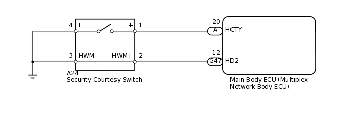
The security courtesy switch is built into the hood lock. This switch turns on when the engine hood is opened and turns off when the engine hood is closed.
WIRING DIAGRAM
INSPECTION PROCEDURE
PROCEDURE
READ VALUE USING INTELLIGENT TESTER (SECURITY COURTESY SWITCH)
Using the intelligent tester, read the Data List.
Body Electrical > Main Body > Data List
Tester Display
Measurement Item
Range
Normal Condition
Diagnostic Note
Hood Courtesy SW
Security courtesy switch
ON or OFF
ON: Engine hood open
OFF: Engine hood closed
-
OK
ON (engine hood open) and OFF (engine hood closed) appear on screen according to condition of engine hood.
Result
Result
OK
NG
NG INSPECT SECURITY COURTESY SWITCHClick here
INSPECT SECURITY COURTESY SWITCH
-
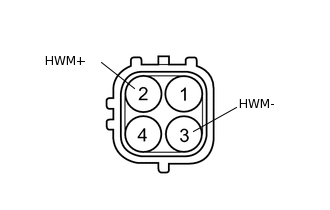
Remove the security courtesy switch.
Measure the resistance according to the value(s) in the table below.
Standard Resistance
Tester Connection
Condition
Specified Condition
2 (HWM+) - 3 (HWM-)
Always
Below 1 Ω
Result
Result
OK
NG
-
CHECK HARNESS AND CONNECTOR (SECURITY COURTESY SWITCH - MAIN BODY ECU AND BODY GROUND)
Disconnect the A24 switch connector.
Disconnect the G47 ECU connector.
Measure the resistance according to the value(s) in the table below.
Standard Resistance
Tester Connection
Condition
Specified Condition
A24-2 (HWM+) - G47-12 (HD2)
Always
Below 1 Ω
A24-3 (HWM-) - Body ground
Always
Below 1 Ω
A24-2 (HWM+) or G47-12 (HD2) - Body ground
Always
10 kΩ or higher
Result
Result
OK
NG
NG REPAIR OR REPLACE HARNESS OR CONNECTOR
INSPECT SECURITY COURTESY SWITCH
-
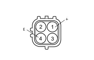
Remove the security courtesy switch.
Measure the resistance according to the value(s) in the table below.
Standard Resistance
Tester Connection
Condition
Specified Condition
1 (+) - 4 (E)
Unlock position
Below 1 Ω
1 (+) - 4 (E)
Lock position
10 kΩ or higher
Result
Result
OK
NG
-
CHECK HARNESS AND CONNECTOR (SECURITY COURTESY SWITCH - MAIN BODY ECU AND BODY GROUND)
Disconnect the A24 switch connector.
Remove the main body ECU.
Measure the resistance according to the value(s) in the table below.
Standard Resistance
Tester Connection
Condition
Specified Condition
A24-1 (+) - A-20 (HCTY)
Always
Below 1 Ω
A24-4 (E) - Body ground
Always
Below 1 Ω
A24-1 (+) or A-20 (HCTY) - Body ground
Always
10 kΩ or higher
Result
Result
OK
NG
NG REPAIR OR REPLACE HARNESS OR CONNECTOR