СИСТЕМА SFI, Diagnostic DTC:P0031, P0032
| DTC Code | DTC Name |
|---|---|
| P0031 | Oxygen (A/F) Sensor Heater Control Circuit Low (Bank 1 Sensor 1) |
| P0032 | Oxygen (A/F) Sensor Heater Control Circuit High (Bank 1 Sensor 1) |
CAUTION / NOTICE / HINT
Tech Tips
-
Although "oxygen sensor" is in the DTC titles, these DTCs are related to the air-fuel ratio (A/F) sensor.
-
Sensor 1 refers to the sensor mounted before the Three-Way Catalytic Converter (TWC) and is located near the engine assembly.
-
Sensor 2 refers to the sensor mounted after the TWC and is located far from the engine assembly.
DESCRIPTION
Refer to DTC P2195 Click here.
Tech Tips
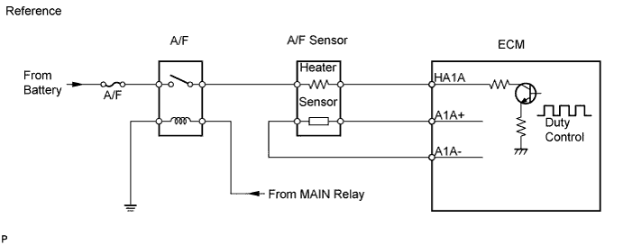
The ECM provides a pulse width modulated control circuit to adjust the current through the heater. The A/F sensor heater circuit uses a relay on the +B side of the circuit.
| DTC No. | DTC Detection Condition | Trouble Area |
|---|---|---|
| P0031 | Heated current is 0.8 A or less when heater operates (1 trip detection logic) |
|
| P0032 | Heated current exceeds 10 A when heater operates (1 trip detection logic) |
|
MONITOR DESCRIPTION
The ECM uses A/F sensor information to keep the air-fuel ratio close to the stoichiometric ratio. This maximizes the catalytic converter's ability to purify exhaust gases. The sensor detects oxygen levels in the exhaust gas and sends this signal to the ECM.
The inner surface of the sensor element is exposed to outside air. The outer surface of the sensor element is exposed to exhaust gas. The sensor element is made of platinum coated zirconia and includes an integrated heating element. The zirconia element generates a small voltage when there is a large difference in the oxygen concentration of the exhaust and outside air. The platinum coating amplifies the voltage generation. When the sensor is heated, the sensor becomes very efficient. If the temperature of the exhaust is low, the sensor will not generate useful voltage signals without supplemental heating. The ECM regulates the supplemental heating using a duty-cycle approach to regulate the average current in the heater element. If the heater current is out of the normal range, the sensor's output signals will be inaccurate and the ECM cannot regulate the A/F properly.
When the heater current is out of the normal operating range, the ECM interprets this as a malfunction and sets a DTC.
WIRING DIAGRAM
Refer to DTC P2195 Click here.
INSPECTION PROCEDURE
Tech Tips
Read freeze frame data using the intelligent tester. Freeze frame data records the engine conditions when malfunctions are detected. When troubleshooting, freeze frame data can help determine if the vehicle was moving or stationary, if the engine was warmed up or not, if the air-fuel ratio was lean or rich, and other data from the time the malfunction occurred.
PROCEDURE
-
INSPECT AIR FUEL RATIO SENSOR (HEATER RESISTANCE)
-
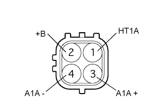
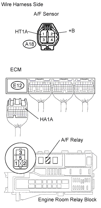
Disconnect the A18 sensor connector.
-
Measure the resistance of the sensor.
Standard resistance Tester Connection Condition Specified Condition 1 (HT1A) - 2 (+B) 20°C (68°F) 1.8 to 3.4 Ω 1 (HT1A) - 4 (A1A-) Always 10 kΩ or higher
NG 
REPLACE AIR FUEL RATIO SENSOR
OK 
-
-
INSPECT A/F RELAY (Marking: A/F)
-
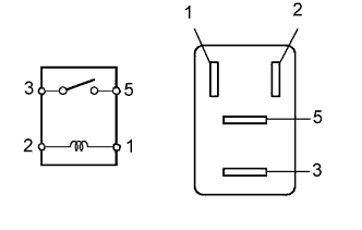
Remove the A/F relay from the engine room relay block.
-
Measure the resistance of the relay.
Standard resistance Tester Connection Specified Condition 3 - 5 10 kΩ or higher 3 - 5 Below 1 Ω
(when battery voltage is applied to terminals 1 and 2)
NG
REPLACE A/F RELAY
OK
-
-
CHECK ECM (HA1A VOLTAGE)
-
Turn the ignition switch ON.
-
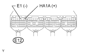
Measure the voltage of the E12 ECM connector.
Standard voltage Tester Connection Specified Condition E12-1 (HA1A) - E12-3 (E1) 9 to 14 V
OK
REPLACE ECM
NG
-
-
CHECK WIRE HARNESS (A/F SENSOR - ECM AND A/F RELAY)
-
Disconnect the A18 A/F sensor connector.
-
Disconnect the E12 ECM connector.
-
Remove the A/F relay from the engine room relay block.
-
Measure the resistance of the wire harness side connectors.
Standard resistance Tester Connection Specified Condition A18-1 (HT1A) - E12-1 (HA1A) Below 1 Ω A18-2 (+B) - R/B A/F relay terminal 3 Below 1 Ω A18-1 (HT1A) or E12-1 (HA1A) - Body ground 10 kΩ or higher A18-2 (+B) or R/B A/F relay terminal 3 - Body ground 10 kΩ or higher
NG
REPAIR OR REPLACE HARNESS AND CONNECTOR
OK 
REPLACE ECM
-