CAN COMMUNICATION SYSTEM
Figure 1. V Bus RHD (Models without Central Gateway ECU)
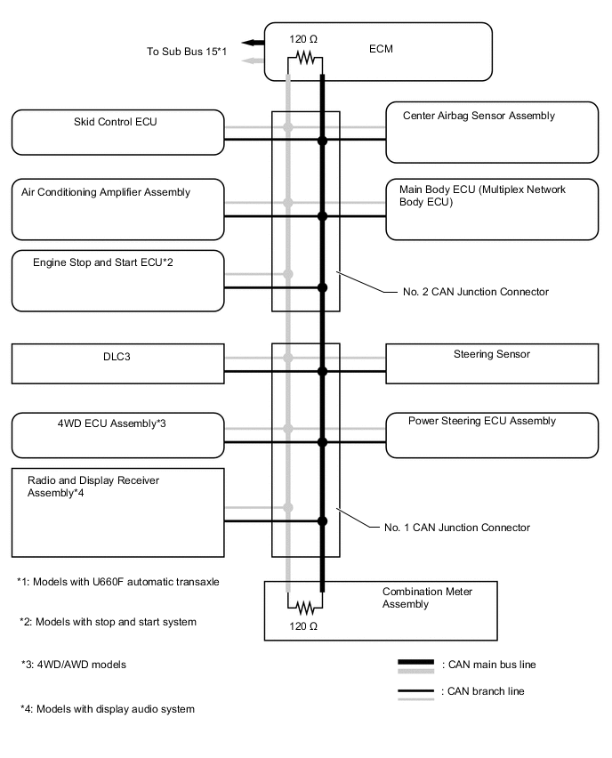
Figure 2. V Bus LHD (Models without Central Gateway ECU)
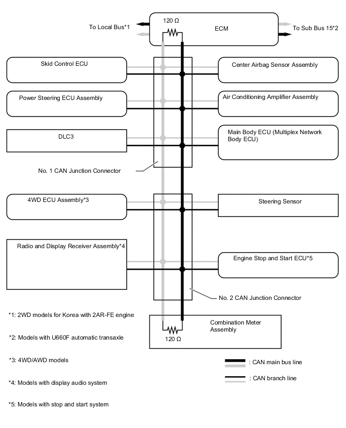
Figure 3. Bus 2 RHD (Models with Central Gateway ECU)
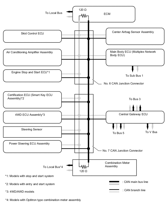
Figure 4. Bus 2 LHD (Models with Central Gateway ECU)
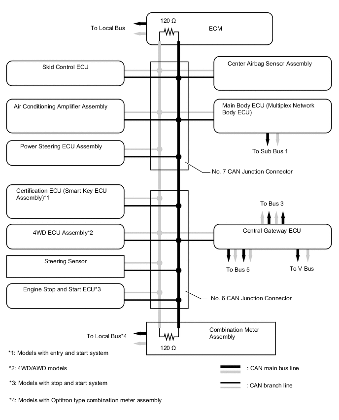
Figure 5. Bus 5 RHD/LHD (Models with Central Gateway ECU)
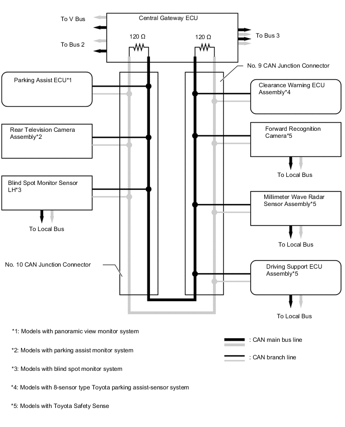
Figure 6. Bus 3 RHD (Models with Central Gateway ECU)

Figure 7. Bus 3 LHD (Models with Central Gateway ECU)
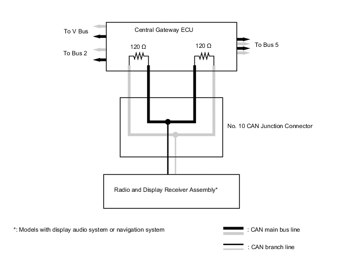
Figure 8. V Bus RHD/LHD (Models with Central Gateway ECU)
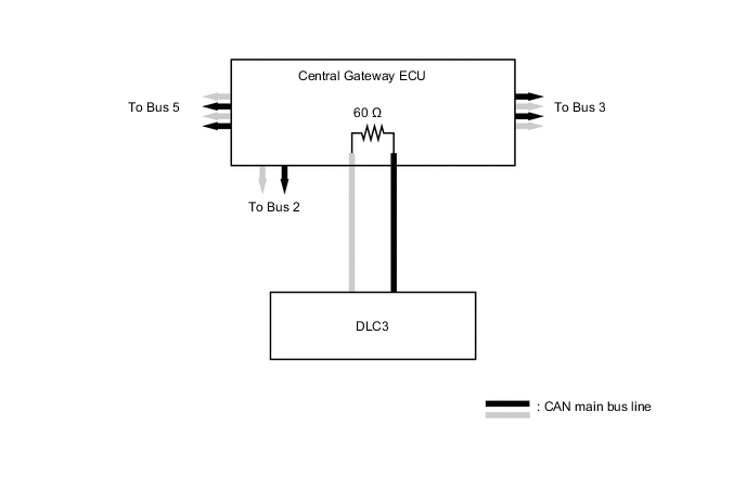
Figure 9. Sub Bus 1 RHD (Models with Central Gateway ECU)
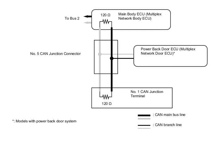
Figure 10. Sub Bus 1 LHD (Models with Central Gateway ECU)
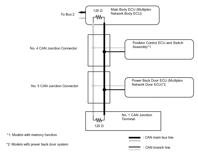
Figure 11. Local Bus (Models with Toyota Safety Sence)
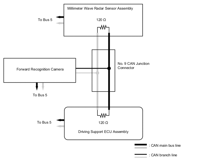
Figure 12. Local Bus (Models with U660F Automatic Transaxle)
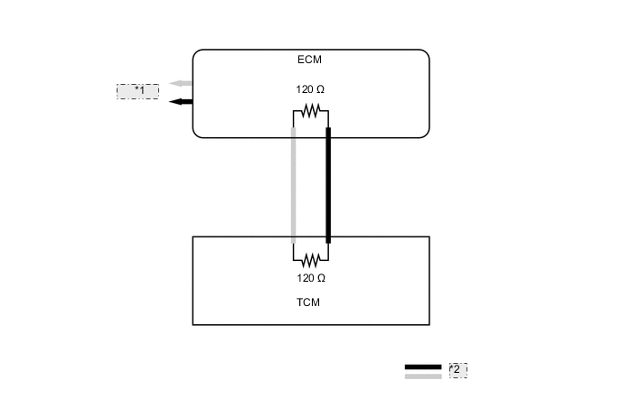
| *1 | To Bus 2 |
| *2 | CAN main bus line |
Figure 13. Local Bus (Models with Blind Spot Monitor System)
| *1 | Blind Spot Monitor Sensor LH |
| *2 | To Bus 5 |
| *3 | Blind Spot Monitor Sensor RH |
| *4 | CAN main bus line |
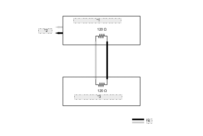
Figure 14. Local Bus (Models with 2WW Engine or 2WD Models for Korea with 2AR-FE Engine )
| *1 | To Bus 2 |
| *2 | Generator Control ECU Assembly |
| *3 | CAN main bus line |
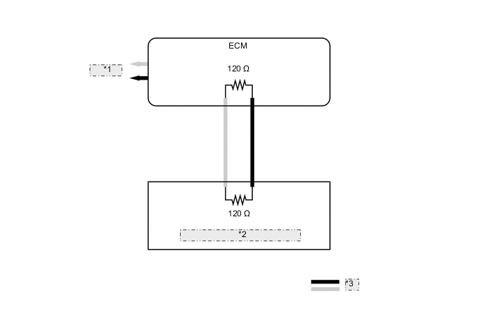
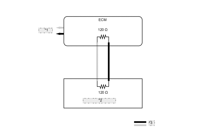
Figure 15. Local Bus (Models with Optitron Type Combination Meter Assembly)
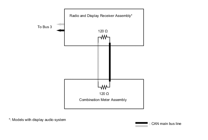
Figure 16. Local Bus (Models with 3ZR-FAE Engine)
| *1 | To Bus 2 |
| *2 | VALVEMATIC Actuator |
| *3 | CAN main bus line |