VEHICLE STABILITY CONTROL SYSTEM, Diagnostic DTC:C1237

| DTC Code | DTC Name |
|---|---|
| C1237 | Speed Sensor Rotor Faulty |
DESCRIPTION
The skid control ECU (brake actuator assembly) measures the speed of each wheel by receiving signals from each speed sensor.
These signals are used for recognizing that all four wheels are operating properly.
Therefore, signals from all wheels must be equal.
| DTC No. | Detection Item | DTC Detection Condition | Trouble Area |
|---|---|---|---|
| C1237 | Speed Sensor Rotor Faulty | Any of the following is detected:
|
|
| Vehicle Condition | |||||
|---|---|---|---|---|---|
| Pattern 1 | Pattern 2 | Pattern 3 | Pattern 4 | ||
| Diagnosis Condition | - | - | - | - | - |
| Malfunction Status | Discrepancy among four wheel speed sensor output. | ○ | - | - | - |
| Abnormal pulse signals. | - | ○ | - | - | |
| Continuous ABS control is performed. | - | - | ○ | - | |
| VSC control is performed. | - | - | - | ○ | |
| Detection Time | - | 3 seconds or more | 60 seconds or more | 10 seconds or more | |
| Number of Trips | 1 trip | 1 trip | 1 trip | 1 trip | |
Tech Tips
DTC will be output when conditions for either of the patterns in the table above are met.
CAUTION / NOTICE / HINT
Note
When replacing the skid control ECU (brake actuator assembly), perform system variant learning.
PROCEDURE
-
RECONFIRM DTC
-
Clear the DTCs.
Chassis > ABS/VSC/TRC/EPB > Clear DTCs -
Turn the ignition switch off.
-
Start the engine.
-
Drive the vehicle at a speed of 54 km/h (34 mph) or more for at least 120 seconds.
-
Check if the same DTC is output.
Chassis > ABS/VSC/TRC/EPB > Trouble CodesResult Result Proceed to C1237 is output A C1237 and C1330, C1331, C1332, C1333, 1464, C1465, C1466, C1467 are output simultaneously B
B 
GO TO DTCS (C1330, C1331, C1332, C1333, 1464, C1465, C1466 and/or C1467) Click here
A 
-
-
CHECK TIRES
-
Check the size and condition of all four tires.
Tech Tips
The DTC is output when tire deformation or a difference in tire size is detected.
OK The diameter of all four tires and the tire pressure are the same. Result Proceed to OK NG
NG
REPLACE TIRES SO THAT ALL FOUR TIRES ARE THE SAME SIZE
OK
-
-
READ VALUE USING GTS (SPEED SENSOR)
-
Connect the GTS to the DLC3.
-
Start the engine.
-
Select the Data List using the GTS.
Chassis > ABS/VSC/TRC/EPB > Data ListTester Display Measurement Item Range Normal Condition Diagnostic Note FR Wheel Speed Front wheel speed sensor RH reading Min.: 0 km/h (0 mph), Max.: 326 km/h (202 mph) Vehicle stopped: 0 km/h (0 mph) When driving at constant speed: No large fluctuations FL Wheel Speed Front wheel speed sensor LH reading Min.: 0 km/h (0 mph), Max.: 326 km/h (202 mph) Vehicle stopped: 0 km/h (0 mph) When driving at constant speed: No large fluctuations RR Wheel Speed Rear wheel speed sensor RH reading Min.: 0 km/h (0 mph), Max.: 326 km/h (202 mph) Vehicle stopped: 0 km/h (0 mph) When driving at constant speed: No large fluctuations RL Wheel Speed Rear wheel speed sensor LH reading Min.: 0 km/h (0 mph), Max.: 326 km/h (202 mph) Vehicle stopped: 0 km/h (0 mph) When driving at constant speed: No large fluctuations
Chassis > ABS/VSC/TRC/EPB > Data ListTester Display FR Wheel Speed FL Wheel Speed RR Wheel Speed RL Wheel Speed -
Check the speed sensor output value.
OK The output value changes in accordance with the vehicle speed. Result Result Proceed to OK A NG (The output value for front speed sensor RH does not change in accordance with the vehicle speed) B NG (The output value for front speed sensor LH does not change in accordance with the vehicle speed) C NG (The output value for rear speed sensor RH does not change in accordance with the vehicle speed) (for 2WD) D NG (The output value for rear speed sensor RH does not change in accordance with the vehicle speed) (for AWD) E NG (The output value for rear speed sensor LH does not change in accordance with the vehicle speed) (for 2WD) F NG (The output value for rear speed sensor LH does not change in accordance with the vehicle speed) (for AWD) G NG (The Test Mode (Signal Check) inspection item for 2 or more sensors does not change from incomplete to complete) (for LHD) H NG (The Test Mode (Signal Check) inspection item for 2 or more sensors does not change from incomplete to complete) (for RHD) I
B 
CHECK FRONT SPEED SENSOR RH INSTALLATION Click here
C
CHECK FRONT SPEED SENSOR LH INSTALLATION Click here
D
CHECK REAR SPEED SENSOR RH INSTALLATION Click here
E
CHECK REAR SPEED SENSOR RH INSTALLATION Click here
F
CHECK REAR SPEED SENSOR LH INSTALLATION Click here
G
CHECK REAR SPEED SENSOR LH INSTALLATION Click here
H
REPLACE BRAKE ACTUATOR ASSEMBLY Click here
I
REPLACE BRAKE ACTUATOR ASSEMBLY Click here
A
-
-
PERFORM TEST MODE INSPECTION (SIGNAL CHECK)
-
Turn the ignition switch off.
-
Perform the sensor check using Test Mode (Signal Check) Procedure.
Chassis > ABS/VSC/TRC/EPB > UtilityTester Display Signal Check OK All Test Mode (Signal Check) inspection items change from incomplete to complete. Result Result Proceed to OK A NG (The Test Mode (Signal Check) inspection item for front speed sensor RH does not change from incomplete to complete) B NG (The Test Mode (Signal Check) inspection item for front speed sensor LH does not change from incomplete to complete) C NG (The Test Mode (Signal Check) inspection item for rear speed sensor RH does not change from incomplete to complete) (for 2WD) D NG (The Test Mode (Signal Check) inspection item for rear speed sensor RH does not change from incomplete to complete) (for AWD) E NG (The Test Mode (Signal Check) inspection item for rear speed sensor LH does not change from incomplete to complete) (for 2WD) F NG (The Test Mode (Signal Check) inspection item for rear speed sensor LH does not change from incomplete to complete) (for AWD) G NG (The Test Mode (Signal Check) inspection item for 2 or more sensors does not change from incomplete to complete) (for LHD) H NG (The Test Mode (Signal Check) inspection item for 2 or more sensors does not change from incomplete to complete) (for RHD) I
A
USE SIMULATION METHOD TO CHECK Click here
C
GO TO STEP 12 Click here
D
GO TO STEP 19 Click here
E
GO TO STEP 26 Click here
F
GO TO STEP 35 Click here
G
GO TO STEP 42 Click here
H
REPLACE BRAKE ACTUATOR ASSEMBLY Click here
I
REPLACE BRAKE ACTUATOR ASSEMBLY Click here
B
-
-
CHECK FRONT SPEED SENSOR RH INSTALLATION
-
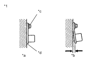
*1 Front Speed Sensor RH *a Correct *b Incorrect *c 8.5 N*m *d No clearance Turn the ignition switch off.
-
Check the speed sensor installation.
OK There is no clearance between the sensor and the front steering knuckle RH. The installation bolt is tightened properly. Torque 8.5 N*m (87 kgf*cm, 75 in.*lbf) Result Proceed to OK NG
NG
REINSTALL OR REPLACE FRONT SPEED SENSOR RH Click here
OK
-
-
CHECK FRONT SPEED SENSOR RH (CHECK FOR FOREIGN MATTER)
-
Remove the front speed sensor RH.
-
Check the speed sensor tip.
OK The sensor tip is free of scratches, oil, and foreign matter. Note
-
If there is oil or foreign matter on the speed sensor, clean the speed sensor.
-
If the speed sensor is damaged, replace the speed sensor with a new one.
-
Check the speed sensor signal after cleaning or replacement.
Result Proceed to OK NG -
NG
CLEAN OR REPLACE FRONT SPEED SENSOR RH
OK
-
-
INSPECT BRAKE ACTUATOR ASSEMBLY (POWER SOURCE CIRCUIT)
-
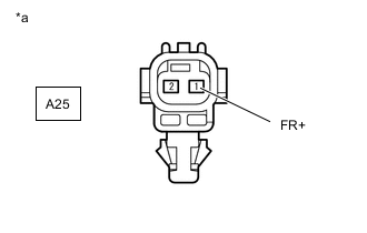
*a Front view of wire harness connector
(to Front Speed Sensor RH)
Make sure that there is no looseness at the locking part and the connecting part of the connectors.
OK The connector is securely connected. -
Disconnect the front speed sensor RH connector.
-
Check both the connector case and the terminals for deformation and corrosion.
OK No deformation or corrosion. -
Turn the ignition switch to ON.
-
Measure the voltage according to the value(s) in the table below.
Standard Voltage Tester Connection Condition Specified Condition A25-1 (FR+) - Body ground Ignition switch ON 11 to 14 V Result Proceed to OK NG
NG
CHECK HARNESS AND CONNECTOR (BRAKE ACTUATOR ASSEMBLY - FRONT SPEED SENSOR RH) Click here
OK
-
-
INSPECT BRAKE ACTUATOR ASSEMBLY (GROUND CIRCUIT)
-

*a Front view of wire harness connector
(to Front Speed Sensor RH)
Measure the voltage according to the value(s) in the table below.
Standard Voltage Tester Connection Condition Specified Condition A25-1 (FR+) - A25-2 (FR-) Ignition switch ON 11 to 14 V Result Proceed to OK NG
NG
CHECK HARNESS AND CONNECTOR (BRAKE ACTUATOR ASSEMBLY - FRONT SPEED SENSOR RH) Click here
OK
-
-
CHECK FRONT SPEED SENSOR ROTOR (FRONT AXLE HUB ASSEMBLY RH) (CHECK FOR FOREIGN MATTER)
-
Remove the front speed sensor rotor (front axle hub assembly RH).
-
Check the speed sensor rotor.
OK The rotor is free of scratches, oil, and foreign matter. Note
-
If there is oil or foreign matter on the speed sensor rotor, clean the speed sensor rotor.
-
If the speed sensor rotor is damaged, replace the speed sensor rotor with a new one.
-
Check the speed sensor signal after cleaning or replacement.
Tech Tips
-
The front speed sensor rotor is incorporated into the front axle hub assembly.
-
If the front speed sensor rotor needs to be replaced, replace it together with the front axle hub assembly.
Result Result Proceed to OK A NG (The speed sensor rotor is damaged.) B NG (There is foreign matter on the speed sensor rotor.) C -
A
REPLACE FRONT SPEED SENSOR RH Click here
B
REPLACE FRONT AXLE HUB SUB-ASSEMBLY RH Click here
C
CLEAN FRONT SPEED SENSOR ROTOR (FRONT AXLE HUB ASSEMBLY RH)
-
-
CHECK HARNESS AND CONNECTOR (BRAKE ACTUATOR ASSEMBLY - FRONT SPEED SENSOR RH)
-
Turn the ignition switch off.
-
Make sure that there is no looseness at the locking part and the connecting part of the connectors.
OK The connector is securely connected. -
Disconnect the A42 skid control ECU (brake actuator assembly) connector.
-
Check both the connector case and the terminals for deformation and corrosion.
OK No deformation or corrosion. -
Measure the resistance according to the value(s) in the table below.
Standard Resistance Tester Connection Condition Specified Condition A42-26 (FR-) - A25-2 (FR-) Always Below 1 Ω A42-26 (FR-) or A25-2 (FR-) - Body ground Always 10 kΩ or higher Result Result Proceed to OK (for LHD) A OK (for RHD) B NG C
A
REPLACE BRAKE ACTUATOR ASSEMBLY Click here
B
REPLACE BRAKE ACTUATOR ASSEMBLY Click here
C
REPAIR OR REPLACE HARNESS OR CONNECTOR
-
-
CHECK FRONT SPEED SENSOR LH INSTALLATION
-
*1 Front Speed Sensor LH *a Correct *b Incorrect *c 8.5 N*m *d No clearance Turn the ignition switch off.
-
Check the speed sensor installation.
OK There is no clearance between the sensor and the front steering knuckle LH. The installation bolt is tightened properly. Torque 8.5 N*m (87 kgf*cm, 75 in.*lbf) Result Proceed to OK NG
NG
REINSTALL OR REPLACE FRONT SPEED SENSOR LH Click here
OK
-
-
CHECK FRONT SPEED SENSOR LH (CHECK FOR FOREIGN MATTER)
-
Remove the front speed sensor LH.
-
Check the speed sensor tip.
OK The sensor tip is free of scratches, oil, and foreign matter. Note
-
If there is oil or foreign matter on the speed sensor, clean the speed sensor.
-
If the speed sensor is damaged, replace the speed sensor with a new one.
-
Check the speed sensor signal after cleaning or replacement.
Result Proceed to OK NG -
NG
CLEAN OR REPLACE FRONT SPEED SENSOR LH
OK
-
-
INSPECT BRAKE ACTUATOR ASSEMBLY (POWER SOURCE CIRCUIT)
-
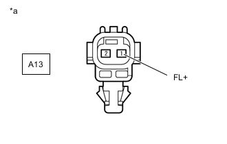
*a Front view of wire harness connector
(to Front Speed Sensor LH)
Make sure that there is no looseness at the locking part and the connecting part of the connectors.
OK The connector is securely connected. -
Disconnect the front speed sensor LH connector.
-
Check both the connector case and the terminals for deformation and corrosion.
OK No deformation or corrosion. -
Turn the ignition switch to ON.
-
Measure the voltage according to the value(s) in the table below.
Standard Voltage Tester Connection Condition Specified Condition A13-1 (FL+) - Body ground Ignition switch ON 11 to 14 V Result Proceed to OK NG
NG
CHECK HARNESS AND CONNECTOR (BRAKE ACTUATOR ASSEMBLY - FRONT SPEED SENSOR LH) Click here
OK
-
-
INSPECT BRAKE ACTUATOR ASSEMBLY (GROUND CIRCUIT)
-
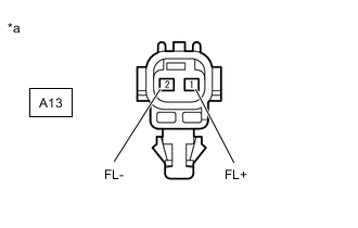
*a Front view of wire harness connector
(to Front Speed Sensor LH)
Measure the voltage according to the value(s) in the table below.
Standard Voltage Tester Connection Condition Specified Condition A13-1 (FL+) - A13-2 (FL-) Ignition switch ON 11 to 14 V Result Proceed to OK NG
NG
CHECK HARNESS AND CONNECTOR (BRAKE ACTUATOR ASSEMBLY - FRONT SPEED SENSOR LH) Click here
OK
-
-
CHECK FRONT SPEED SENSOR ROTOR (FRONT AXLE HUB ASSEMBLY LH) (CHECK FOR FOREIGN MATTER)
-
Remove the front speed sensor rotor (front axle hub assembly LH).
-
Check the speed sensor rotor.
OK The rotor is free of scratches, oil, and foreign matter. Note
-
If there is oil or foreign matter on the speed sensor rotor, clean the speed sensor rotor.
-
If the speed sensor rotor is damaged, replace the speed sensor rotor with a new one.
-
Check the speed sensor signal after cleaning or replacement.
Tech Tips
-
The front speed sensor rotor is incorporated into the front axle hub assembly.
-
If the front speed sensor rotor needs to be replaced, replace it together with the front axle hub assembly.
Result Result Proceed to OK A NG (The speed sensor rotor is damaged.) B NG (There is foreign matter on the speed sensor rotor.) C -
A
REPLACE FRONT SPEED SENSOR LH Click here
B
REPLACE FRONT AXLE HUB SUB-ASSEMBLY LH Click here
C
CLEAN FRONT SPEED SENSOR ROTOR (FRONT AXLE HUB ASSEMBLY RH)
-
-
CHECK HARNESS AND CONNECTOR (BRAKE ACTUATOR ASSEMBLY - FRONT SPEED SENSOR LH)
-
Turn the ignition switch off.
-
Make sure that there is no looseness at the locking part and the connecting part of the connectors.
OK The connector is securely connected. -
Disconnect the A42 skid control ECU (brake actuator assembly) connector.
-
Check both the connector case and the terminals for deformation and corrosion.
OK No deformation or corrosion. -
Measure the resistance according to the value(s) in the table below.
Standard Resistance Tester Connection Condition Specified Condition A42-7 (FL-) - A13-2 (FL-) Always Below 1 Ω A42-7 (FL-) or A13-2 (FR-) - Body ground Always 10 kΩ or higher Result Result Proceed to OK (for LHD) A OK (for RHD) B NG C
A
REPLACE BRAKE ACTUATOR ASSEMBLY Click here
B
REPLACE BRAKE ACTUATOR ASSEMBLY Click here
C
REPAIR OR REPLACE HARNESS OR CONNECTOR
-
-
CHECK REAR SPEED SENSOR RH INSTALLATION
-
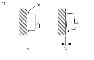
*1 Rear Speed Sensor RH *a OK *b NG *c No Clearance Turn the ignition switch off.
-
Check the speed sensor installation.
OK There is no clearance between the sensor and the rear axle hub. Tech Tips
Because the rear axle hub and bearing assembly RH cannot be disassembled, if the rear speed sensor needs replacement, replace the rear axle hub and bearing assembly RH.
Result Proceed to OK NG
NG
REPLACE REAR AXLE HUB AND BEARING ASSEMBLY RH Click here
OK
-
-
INSPECT BRAKE ACTUATOR ASSEMBLY (POWER SOURCE CIRCUIT)
-

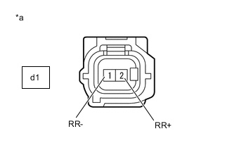
*a Front view of wire harness connector
(to Rear Speed Sensor RH)
Make sure that there is no looseness at the locking part and the connecting part of the connectors.
OK The connector is securely connected. -
Disconnect the rear speed sensor RH connector.
-
Check both the connector case and the terminals for deformation and corrosion.
OK No deformation or corrosion. -
Turn the ignition switch to ON.
-
Measure the voltage according to the value(s) in the table below.
Standard Voltage Tester Connection Condition Specified Condition d1-2 (RR+) - Body ground Ignition switch ON 11 to 14 V Result Proceed to OK NG
NG
INSPECT SKID CONTROL SENSOR WIRE RH (NO. 1 PARKING BRAKE WIRE ASSEMBLY) Click here
OK
-
-
INSPECT BRAKE ACTUATOR ASSEMBLY (GROUND CIRCUIT)
-
*a Front view of wire harness connector
(to Rear Speed Sensor RH)
Measure the voltage according to the value(s) in the table below.
Standard Voltage Tester Connection Condition Specified Condition d1-2 (RR+) - d1-1 (RR-) Ignition switch ON 11 to 14 V Result Proceed to OK NG
OK
REPLACE REAR AXLE HUB AND BEARING ASSEMBLY RH Click here
NG
INSPECT SKID CONTROL SENSOR WIRE RH (NO. 1 PARKING BRAKE WIRE ASSEMBLY) Click here
-
-
INSPECT SKID CONTROL SENSOR WIRE RH (NO. 1 PARKING BRAKE WIRE ASSEMBLY)
-
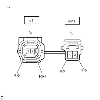
*1 Skid Control Sensor Wire RH (No. 1 Parking Brake Wire Assembly) *a Front view of wire harness connector
(to Sensor Side Connector)
*b Front view of wire harness connector
(to Vehicle Side Connector)
Turn the ignition switch off.
-
Make sure that there is no looseness at the locking part and the connecting part of the connectors.
OK The connector is securely connected. -
Remove the skid control sensor wire RH (No. 1 parking brake wire assembly).
-
Check both the connector case and the terminals for deformation and corrosion.
OK No deformation or corrosion. -
Measure the resistance according to the value(s) in the table below.
Standard Resistance Tester Connection Condition Specified Condition d1-1 (RR-) - dM1-2 (RR-) Always Below 1 Ω d1-1 (RR-) - dM1-1 (RR+) Always 10 kΩ or higher d1-1 (RR-) or dM1-2 (RR-) - Body ground Always 10 kΩ or higher Result Proceed to OK NG
NG
REPLACE SKID CONTROL SENSOR WIRE RH (NO. 1 PARKING BRAKE WIRE ASSEMBLY)
OK
-
-
CHECK HARNESS AND CONNECTOR (BRAKE ACTUATOR ASSEMBLY - SKID CONTROL SENSOR WIRE RH (NO. 1 PARKING BRAKE WIRE ASSEMBLY))
-
Make sure that there is no looseness at the locking part and the connecting part of the connector.
OK The connector is securely connected. -
Disconnect the A42 skid control ECU (brake actuator assembly) connector.
-
Check both the connector case and the terminals for deformation and corrosion.
OK No deformation or corrosion. -
Measure the resistance according to the value(s) in the table below.
Standard Resistance Tester Connection Condition Specified Condition A42-37 (RR-) - dM1-2 (RR-) Always Below 1 Ω A42-37 (RR-) or dM1-2 (RR-) - Body ground Always 10 kΩ or higher Result Result Proceed to OK (for LHD) A OK (for RHD) B NG C
A
REPLACE BRAKE ACTUATOR ASSEMBLY Click here
B
REPLACE BRAKE ACTUATOR ASSEMBLY Click here
C
REPAIR OR REPLACE HARNESS OR CONNECTOR
-
-
INSPECT SKID CONTROL SENSOR WIRE RH (NO. 1 PARKING BRAKE WIRE ASSEMBLY)
-
*1 Skid Control Sensor Wire RH (No. 1 Parking Brake Wire Assembly) *a Front view of wire harness connector
(to Sensor Side Connector)
*b Front view of wire harness connector
(to Vehicle Side Connector)
Turn the ignition switch off.
-
Make sure that there is no looseness at the locking part and the connecting part of the connectors.
OK The connector is securely connected. -
Remove the skid control sensor wire RH (No. 1 parking brake wire assembly).
-
Check both the connector case and the terminals for deformation and corrosion.
OK No deformation or corrosion. -
Measure the resistance according to the value(s) in the table below.
Standard Resistance Tester Connection Condition Specified Condition d1-1 (RR-) - dM1-2 (RR-) Always Below 1 Ω d1-1 (RR-) - dM1-1 (RR+) Always 10 kΩ or higher d1-1 (RR-) or dM1-2 (RR-) - Body ground Always 10 kΩ or higher Result Proceed to OK NG
NG
REPLACE SKID CONTROL SENSOR WIRE RH (NO. 1 PARKING BRAKE WIRE ASSEMBLY)
OK
-
-
CHECK HARNESS AND CONNECTOR (BRAKE ACTUATOR ASSEMBLY - SKID CONTROL SENSOR WIRE RH (NO. 1 PARKING BRAKE WIRE ASSEMBLY))
-
Make sure that there is no looseness at the locking part and the connecting part of the connector.
OK The connector is securely connected. -
Disconnect the A42 skid control ECU (brake actuator assembly) connector.
-
Check both the connector case and the terminals for deformation and corrosion.
OK No deformation or corrosion. -
Measure the resistance according to the value(s) in the table below.
Standard Resistance Tester Connection Condition Specified Condition A42-37 (RR-) - dM1-2 (RR-) Always Below 1 Ω A42-37 (RR-) or dM1-2 (RR-) - Body ground Always 10 kΩ or higher Result Result Proceed to OK (for LHD) A OK (for RHD) B NG C
A
REPLACE BRAKE ACTUATOR ASSEMBLY Click here
B
REPLACE BRAKE ACTUATOR ASSEMBLY Click here
C
REPAIR OR REPLACE HARNESS OR CONNECTOR
-
-
CHECK REAR SPEED SENSOR RH INSTALLATION
-
*1 Rear Speed Sensor RH *a Correct *b Incorrect *c 8.5 N*m *d No clearance Turn the ignition switch off.
-
Check the speed sensor installation.
OK There is no clearance between the sensor and the rear axle carrier sub-assembly RH. The installation bolt is tightened properly. Torque 8.5 N*m (87 kgf*cm, 75 in.*lbf) Result Proceed to OK NG
NG
REINSTALL OR REPLACE REAR SPEED SENSOR RH Click here
OK
-
-
CHECK REAR SPEED SENSOR RH (CHECK FOR FOREIGN MATTER)
-
Remove the rear speed sensor RH.
-
Check the speed sensor tip.
OK The sensor tip is free of scratches, oil, and foreign matter. Note
-
If there is oil or foreign matter on the speed sensor, clean the speed sensor.
-
If the speed sensor is damaged, replace the speed sensor with a new one.
-
Check the speed sensor signal after cleaning or replacement.
Result Proceed to OK NG -
NG
CLEAN OR REPLACE REAR SPEED SENSOR RH
OK
-
-
INSPECT BRAKE ACTUATOR ASSEMBLY (POWER SOURCE CIRCUIT)
-
*a Front view of wire harness connector
(to Rear Speed Sensor RH)
Make sure that there is no looseness at the locking part and the connecting part of the connectors.
OK The connector is securely connected. -
Disconnect the rear speed sensor RH connector.
-
Check both the connector case and the terminals for deformation and corrosion.
OK No deformation or corrosion. -
Turn the ignition switch to ON.
-
Measure the voltage according to the value(s) in the table below.
Standard Voltage Tester Connection Condition Specified Condition d1-2 (RR+) - Body ground Ignition switch ON 11 to 14 V Result Proceed to OK NG
NG
INSPECT SKID CONTROL SENSOR WIRE RH (NO. 1 PARKING BRAKE WIRE ASSEMBLY) Click here
OK
-
-
INSPECT BRAKE ACTUATOR ASSEMBLY (GROUND CIRCUIT)
-
*a Front view of wire harness connector
(to Rear Speed Sensor RH)
Measure the voltage according to the value(s) in the table below.
Standard Voltage Tester Connection Condition Specified Condition d1-2 (RR+) - d1-1 (RR-) Ignition switch ON 11 to 14 V Result Proceed to OK NG
NG
INSPECT SKID CONTROL SENSOR WIRE RH (NO. 1 PARKING BRAKE WIRE ASSEMBLY) Click here
OK
-
-
CHECK REAR SPEED SENSOR ROTOR (REAR AXLE HUB AND BEARING ASSEMBLY RH) (CHECK FOR FOREIGN MATTER)
-
Remove the rear speed sensor rotor (rear axle hub and bearing assembly RH).
-
Check the speed sensor rotor.
OK The rotor is free of scratches, oil, and foreign matter. Note
-
If there is oil or foreign matter on the speed sensor rotor, clean the speed sensor rotor.
-
If the speed sensor rotor is damaged, replace the speed sensor rotor with a new one.
-
Check the speed sensor signal after cleaning or replacement.
Tech Tips
-
The rear speed sensor rotor is incorporated into the rear axle hub and bearing assembly RH.
-
If the rear speed sensor rotor needs to be replaced, replace it together with the rear axle hub and bearing assembly RH.
Result Result Proceed to OK A NG (The speed sensor rotor is damaged.) B NG (There is foreign matter on the speed sensor rotor.) C -
A
REPLACE REAR SPEED SENSOR RH Click here
B
REPLACE REAR AXLE HUB AND BEARING ASSEMBLY RH Click here
C
CLEAN REAR SPEED SENSOR ROTOR (REAR AXLE HUB AND BEARING ASSEMBLY RH)
-
-
INSPECT SKID CONTROL SENSOR WIRE RH (NO. 1 PARKING BRAKE WIRE ASSEMBLY)
-
*1 Skid Control Sensor Wire RH (No. 1 Parking Brake Wire Assembly) *a Front view of wire harness connector
(to Sensor Side Connector)
*b Front view of wire harness connector
(to Vehicle Side Connector)
Turn the ignition switch off.
-
Make sure that there is no looseness at the locking part and the connecting part of the connectors.
OK The connector is securely connected. -
Remove the skid control sensor wire RH (No. 1 parking brake wire assembly).
-
Check both the connector case and the terminals for deformation and corrosion.
OK No deformation or corrosion. -
Measure the resistance according to the value(s) in the table below.
Standard Resistance Tester Connection Condition Specified Condition d1-1 (RR-) - dM1-2 (RR-) Always Below 1 Ω d1-1 (RR-) - dM1-1 (RR+) Always 10 kΩ or higher d1-1 (RR-) or dM1-2 (RR-) - Body ground Always 10 kΩ or higher Result Proceed to OK NG
NG
REPLACE SKID CONTROL SENSOR WIRE RH (NO. 1 PARKING BRAKE WIRE ASSEMBLY)
OK
-
-
CHECK HARNESS AND CONNECTOR (BRAKE ACTUATOR ASSEMBLY - SKID CONTROL SENSOR WIRE RH (NO. 1 PARKING BRAKE WIRE ASSEMBLY))
-
Make sure that there is no looseness at the locking part and the connecting part of the connector.
OK The connector is securely connected. -
Disconnect the A42 skid control ECU (brake actuator assembly) connector.
-
Check both the connector case and the terminals for deformation and corrosion.
OK No deformation or corrosion. -
Measure the resistance according to the value(s) in the table below.
Standard Resistance Tester Connection Condition Specified Condition A42-37 (RR-) - dM1-2 (RR-) Always Below 1 Ω A42-37 (RR-) or dM1-2 (RR-) - Body ground Always 10 kΩ or higher Result Result Proceed to OK (for LHD) A OK (for RHD) B NG C
A
REPLACE BRAKE ACTUATOR ASSEMBLY Click here
B
REPLACE BRAKE ACTUATOR ASSEMBLY Click here
C
REPAIR OR REPLACE HARNESS OR CONNECTOR
-
-
CHECK REAR SPEED SENSOR LH INSTALLATION
-
*1 Rear Speed Sensor LH *a OK *b NG *c No Clearance Turn the ignition switch off.
-
Check the speed sensor installation.
OK There is no clearance between the sensor and the rear axle hub. Tech Tips
Because the rear axle hub and bearing assembly LH cannot be disassembled, if the rear speed sensor needs replacement, replace the rear axle hub and bearing assembly LH.
Result Proceed to OK NG
NG
REPLACE REAR AXLE HUB AND BEARING ASSEMBLY LH Click here
OK
-
-
INSPECT BRAKE ACTUATOR ASSEMBLY (POWER SOURCE CIRCUIT)
-
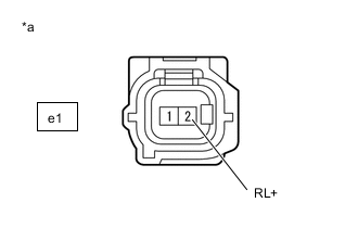
*a Front view of wire harness connector
(to Rear Speed Sensor LH)
Make sure that there is no looseness at the locking part and the connecting part of the connectors.
OK The connector is securely connected. -
Disconnect the rear speed sensor LH connector.
-
Check both the connector case and the terminals for deformation and corrosion.
OK No deformation or corrosion. -
Turn the ignition switch to ON.
-
Measure the voltage according to the value(s) in the table below.
Standard Voltage Tester Connection Condition Specified Condition e1-2 (RL+) - Body ground Ignition switch ON 11 to 14 V Result Proceed to OK NG
NG
INSPECT SKID CONTROL SENSOR WIRE LH (NO. 2 PARKING BRAKE WIRE ASSEMBLY) Click here
OK
-
-
INSPECT BRAKE ACTUATOR ASSEMBLY (GROUND CIRCUIT)
-
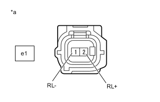
*a Front view of wire harness connector
(to Rear Speed Sensor LH)
Measure the voltage according to the value(s) in the table below.
Standard Voltage Tester Connection Condition Specified Condition e1-2 (RL+) - e1-1 (RL-) Ignition switch ON 11 to 14 V Result Proceed to OK NG
OK
REPLACE REAR AXLE HUB AND BEARING ASSEMBLY LH Click here
NG
INSPECT SKID CONTROL SENSOR WIRE LH (NO. 2 PARKING BRAKE WIRE ASSEMBLY) Click here
-
-
INSPECT SKID CONTROL SENSOR WIRE LH (NO. 2 PARKING BRAKE WIRE ASSEMBLY)
-
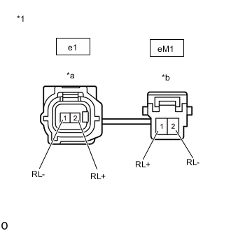
*1 Skid Control Sensor Wire LH (No. 2 Parking Brake Wire Assembly) *a Front view of wire harness connector
(to Sensor Side Connector)
*b Front view of wire harness connector
(to Vehicle Side Connector)
Turn the ignition switch off.
-
Make sure that there is no looseness at the locking part and the connecting part of the connectors.
OK The connector is securely connected. -
Remove the skid control sensor wire LH (No. 2 parking brake wire assembly).
-
Check both the connector case and the terminals for deformation and corrosion.
OK No deformation or corrosion. -
Measure the resistance according to the value(s) in the table below.
Standard Resistance Tester Connection Condition Specified Condition e1-1 (RL-) - eM1-2 (RL-) Always Below 1 Ω e1-1 (RL-) - eM1-1 (RL+) Always 10 kΩ or higher e1-1 (RL-) or eM1-2 (RL-) - Body ground Always 10 kΩ or higher Result Proceed to OK NG
NG
REPLACE SKID CONTROL SENSOR WIRE LH (NO. 2 PARKING BRAKE WIRE ASSEMBLY)
OK
-
-
CHECK HARNESS AND CONNECTOR (BRAKE ACTUATOR ASSEMBLY - SKID CONTROL SENSOR WIRE LH (NO. 2 PARKING BRAKE WIRE ASSEMBLY))
-
Make sure that there is no looseness at the locking part and the connecting part of the connector.
OK The connector is securely connected. -
Disconnect the A42 skid control ECU (brake actuator assembly) connector.
-
Check both the connector case and the terminals for deformation and corrosion.
OK No deformation or corrosion. -
Measure the resistance according to the value(s) in the table below.
Standard Resistance Tester Connection Condition Specified Condition A42-23 (RL-) - eM1-2 (RL-) Always Below 1 Ω A42-23 (RL-) or eM1-2 (RL-) - Body ground Always 10 kΩ or higher Result Result Proceed to OK (for LHD) A OK (for RHD) B NG C
A
REPLACE BRAKE ACTUATOR ASSEMBLY Click here
B
REPLACE BRAKE ACTUATOR ASSEMBLY Click here
C
REPAIR OR REPLACE HARNESS OR CONNECTOR
-
-
INSPECT SKID CONTROL SENSOR WIRE LH (NO. 2 PARKING BRAKE WIRE ASSEMBLY)
-
*1 Skid Control Sensor Wire LH (No. 2 Parking Brake Wire Assembly) *a Front view of wire harness connector
(to Sensor Side Connector)
*b Front view of wire harness connector
(to Vehicle Side Connector)
Turn the ignition switch off.
-
Make sure that there is no looseness at the locking part and the connecting part of the connectors.
OK The connector is securely connected. -
Remove the skid control sensor wire LH (No. 2 parking brake wire assembly).
-
Check both the connector case and the terminals for deformation and corrosion.
OK No deformation or corrosion. -
Measure the resistance according to the value(s) in the table below.
Standard Resistance Tester Connection Condition Specified Condition e1-1 (RL-) - eM1-2 (RL-) Always Below 1 Ω e1-1 (RL-) - eM1-1 (RL+) Always 10 kΩ or higher e1-1 (RL-) or eM1-2 (RL-) - Body ground Always 10 kΩ or higher Result Proceed to OK NG
NG
REPLACE SKID CONTROL SENSOR WIRE LH (NO. 2 PARKING BRAKE WIRE ASSEMBLY)
OK
-
-
CHECK HARNESS AND CONNECTOR (BRAKE ACTUATOR ASSEMBLY - SKID CONTROL SENSOR WIRE LH (NO. 2 PARKING BRAKE WIRE ASSEMBLY))
-
Make sure that there is no looseness at the locking part and the connecting part of the connector.
OK The connector is securely connected. -
Disconnect the A42 skid control ECU (brake actuator assembly) connector.
-
Check both the connector case and the terminals for deformation and corrosion.
OK No deformation or corrosion. -
Measure the resistance according to the value(s) in the table below.
Standard Resistance Tester Connection Condition Specified Condition A42-23 (RL-) - eM1-2 (RL-) Always Below 1 Ω A42-23 (RL-) or eM1-2 (RL-) - Body ground Always 10 kΩ or higher Result Result Proceed to OK (for LHD) A OK (for RHD) B NG C
A
REPLACE BRAKE ACTUATOR ASSEMBLY Click here
B
REPLACE BRAKE ACTUATOR ASSEMBLY Click here
C
REPAIR OR REPLACE HARNESS OR CONNECTOR
-
-
CHECK REAR SPEED SENSOR LH INSTALLATION
-
*1 Rear Speed Sensor LH *a Correct *b Incorrect *c 8.5 N*m *d No clearance Turn the ignition switch off.
-
Check the speed sensor installation.
OK There is no clearance between the sensor and the rear axle carrier sub-assembly LH. The installation bolt is tightened properly. Torque 8.5 N*m (87 kgf*cm, 75 in.*lbf) Result Proceed to OK NG
NG
REINSTALL OR REPLACE REAR SPEED SENSOR RH Click here
OK
-
-
CHECK REAR SPEED SENSOR LH (CHECK FOR FOREIGN MATTER)
-
Remove the rear speed sensor LH.
-
Check the speed sensor tip.
OK The sensor tip is free of scratches, oil, and foreign matter. Note
-
If there is oil or foreign matter on the speed sensor, clean the speed sensor.
-
If the speed sensor is damaged, replace the speed sensor with a new one.
-
Check the speed sensor signal after cleaning or replacement.
Result Proceed to OK NG -
NG
CLEAN OR REPLACE REAR SPEED SENSOR LH
OK
-
-
INSPECT BRAKE ACTUATOR ASSEMBLY (POWER SOURCE CIRCUIT)
-
*a Front view of wire harness connector
(to Rear Speed Sensor RH)
Make sure that there is no looseness at the locking part and the connecting part of the connectors.
OK The connector is securely connected. -
Disconnect the rear speed sensor LH connector.
-
Check both the connector case and the terminals for deformation and corrosion.
OK No deformation or corrosion. -
Turn the ignition switch to ON.
-
Measure the voltage according to the value(s) in the table below.
Standard Voltage Tester Connection Condition Specified Condition e1-2 (RL+) - Body ground Ignition switch ON 11 to 14 V Result Proceed to OK NG
NG
INSPECT SKID CONTROL SENSOR WIRE LH (NO. 2 PARKING BRAKE WIRE ASSEMBLY) Click here
OK
-
-
INSPECT BRAKE ACTUATOR ASSEMBLY (GROUND CIRCUIT)
-
*a Front view of wire harness connector
(to Rear Speed Sensor LH)
Measure the voltage according to the value(s) in the table below.
Standard Voltage Tester Connection Condition Specified Condition e1-2 (RL+) - e1-1 (RL-) Ignition switch ON 11 to 14 V Result Proceed to OK NG
NG
INSPECT SKID CONTROL SENSOR WIRE LH (NO. 2 PARKING BRAKE WIRE ASSEMBLY) Click here
OK
-
-
CHECK REAR SPEED SENSOR ROTOR (REAR AXLE HUB AND BEARING ASSEMBLY LH) (CHECK FOR FOREIGN MATTER)
-
Remove the rear speed sensor rotor (rear axle hub and bearing assembly LH).
-
Check the speed sensor rotor.
OK The rotor is free of scratches, oil, and foreign matter. Note
-
If there is oil or foreign matter on the speed sensor rotor, clean the speed sensor rotor.
-
If the speed sensor rotor is damaged, replace the speed sensor rotor with a new one.
-
Check the speed sensor signal after cleaning or replacement.
Tech Tips
-
The rear speed sensor rotor is incorporated into the rear axle hub and bearing assembly LH.
-
If the rear speed sensor rotor needs to be replaced, replace it together with the rear axle hub and bearing assembly LH.
Result Result Proceed to OK A NG (The speed sensor rotor is damaged.) B NG (There is foreign matter on the speed sensor rotor.) C -
A
REPLACE REAR SPEED SENSOR LH Click here
B
REPLACE REAR AXLE HUB AND BEARING ASSEMBLY LH Click here
C
CLEAN REAR SPEED SENSOR ROTOR (REAR AXLE HUB AND BEARING ASSEMBLY LH)
-
-
INSPECT SKID CONTROL SENSOR WIRE LH (NO. 2 PARKING BRAKE WIRE ASSEMBLY)
-
*1 Skid Control Sensor Wire LH (No. 2 Parking Brake Wire Assembly) *a Front view of wire harness connector
(to Sensor Side Connector)
*b Front view of wire harness connector
(to Vehicle Side Connector)
Turn the ignition switch off.
-
Make sure that there is no looseness at the locking part and the connecting part of the connectors.
OK The connector is securely connected. -
Remove the skid control sensor wire LH (No. 2 parking brake wire assembly).
-
Check both the connector case and the terminals for deformation and corrosion.
OK No deformation or corrosion. -
Measure the resistance according to the value(s) in the table below.
Standard Resistance Tester Connection Condition Specified Condition e1-1 (RL-) - eM1-2 (RL-) Always Below 1 Ω e1-1 (RL-) - eM1-1 (RL+) Always 10 kΩ or higher e1-1 (RL-) or eM1-2 (RL-) - Body ground Always 10 kΩ or higher Result Proceed to OK NG
NG
REPLACE SKID CONTROL SENSOR WIRE LH (NO. 2 PARKING BRAKE WIRE ASSEMBLY)
OK
-
-
CHECK HARNESS AND CONNECTOR (BRAKE ACTUATOR ASSEMBLY - SKID CONTROL SENSOR WIRE LH (NO. 2 PARKING BRAKE WIRE ASSEMBLY))
-
Make sure that there is no looseness at the locking part and the connecting part of the connector.
OK The connector is securely connected. -
Disconnect the A42 skid control ECU (brake actuator assembly) connector.
-
Check both the connector case and the terminals for deformation and corrosion.
OK No deformation or corrosion. -
Measure the resistance according to the value(s) in the table below.
Standard Resistance Tester Connection Condition Specified Condition A42-23 (RL-) - eM1-2 (RL-) Always Below 1 Ω A42-23 (RL-) or eM1-2 (RL-) - Body ground Always 10 kΩ or higher Result Result Proceed to OK (for LHD) A OK (for RHD) B NG C
A
REPLACE BRAKE ACTUATOR ASSEMBLY Click here
B
REPLACE BRAKE ACTUATOR ASSEMBLY Click here
C
REPAIR OR REPLACE HARNESS OR CONNECTOR
-
-
INSPECT SKID CONTROL SENSOR WIRE LH (NO. 2 PARKING BRAKE WIRE ASSEMBLY)
-
*1 Skid Control Sensor Wire LH (No. 2 Parking Brake Wire Assembly) *a Front view of wire harness connector
(to Sensor Side Connector)
*b Front view of wire harness connector
(to Vehicle Side Connector)
Turn the ignition switch off.
-
Make sure that there is no looseness at the locking part and the connecting part of the connectors.
OK The connector is securely connected. -
Remove the skid control sensor wire LH (No. 2 parking brake wire assembly).
-
Check both the connector case and the terminals for deformation and corrosion.
OK No deformation or corrosion. -
Measure the resistance according to the value(s) in the table below.
Standard Resistance Tester Connection Condition Specified Condition e1-1 (RL-) - eM1-2 (RL-) Always Below 1 Ω e1-1 (RL-) - eM1-1 (RL+) Always 10 kΩ or higher e1-1 (RL-) or eM1-2 (RL-) - Body ground Always 10 kΩ or higher Result Proceed to OK NG
NG
REPLACE SKID CONTROL SENSOR WIRE LH (NO. 2 PARKING BRAKE WIRE ASSEMBLY)
OK
-
-
CHECK HARNESS AND CONNECTOR (BRAKE ACTUATOR ASSEMBLY - SKID CONTROL SENSOR WIRE LH (NO. 2 PARKING BRAKE WIRE ASSEMBLY))
-
Make sure that there is no looseness at the locking part and the connecting part of the connector.
OK The connector is securely connected. -
Disconnect the A42 skid control ECU (brake actuator assembly) connector.
-
Check both the connector case and the terminals for deformation and corrosion.
OK No deformation or corrosion. -
Measure the resistance according to the value(s) in the table below.
Standard Resistance Tester Connection Condition Specified Condition A42-23 (RL-) - eM1-2 (RL-) Always Below 1 Ω A42-23 (RL-) or eM1-2 (RL-) - Body ground Always 10 kΩ or higher Result Result Proceed to OK (for LHD) A OK (for RHD) B NG C
A
REPLACE BRAKE ACTUATOR ASSEMBLY Click here
B
REPLACE BRAKE ACTUATOR ASSEMBLY Click here
C
REPAIR OR REPLACE HARNESS OR CONNECTOR
-