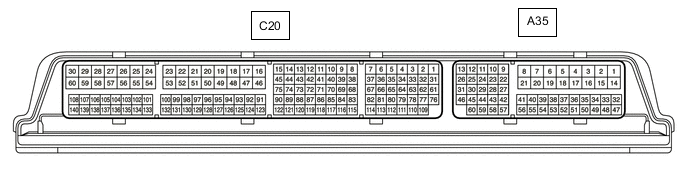
CRUISE CONTROL SYSTEM(for 8AR-FTS) TERMINALS OF ECU
-
CHECK ECM
Terminal No.
(Symbol)
Wiring Color Terminal Description Condition Specified Condition A35-1 (BATT) - C20-53 (E1) L - W-B Constant power source Always 11 to 14 V A35-10 (ST1-) - C20-53 (E1) G - W-B Stop light signal Engine switch on (IG), brake pedal depressed 0 to 1.5 V Engine switch on (IG), brake pedal released 7.5 to 14 V A35-9 (STP) - C20-53 (E1) L - W-B Stop light signal Brake pedal depressed 7.5 to 14 V Brake pedal released 0 to 1.5 V A35-43 (SFTD) - C20-53 (E1) GR - W-B Down shift switch signal Engine switch on (IG), shift lever in S 11 to 14 V Engine switch on (IG), shift lever in (-) Below 1 V A35-42 (SFTU) - C20-53 (E1) LG - W-B Up shift switch signal Engine switch on (IG), shift lever in S 11 to 14 V Engine switch on (IG), shift lever in (+) Below 1 V C20-34 (D) - C20-53 (E1) B - W-B D shift position signal Engine switch on (IG), shift lever in D 11 to 14 V Engine switch on (IG) and shift lever except D Below 1 V A35-55 (CCS) - C20-53 (E1) V - W-B Cruise control switch circuit Cruise control main switch off 1 MΩ or higher Cruise control main switch on Below 2.5 Ω +RES switch on 236 to 244 Ω -SET switch on 618 to 642 Ω CANCEL switch on 1510 to 1570 Ω