BRAKE BOOSTER(for RHD) INSTALLATION
PROCEDURE
INSTALL VACUUM SENSOR GROMMET (w/ Stop And Start System)
Install a new vacuum sensor grommet to the brake booster assembly.
INSTALL VACUUM SENSOR ASSEMBLY (w/ Stop And Start System)
Install the vacuum sensor assembly to the vacuum sensor grommet.
INSTALL CHECK VALVE GROMMET
Install a new check valve grommet to the brake booster assembly.
INSTALL BRAKE VACUUM CHECK VALVE ASSEMBLY
Install the brake vacuum check valve assembly to the check valve grommet.
INSTALL BRAKE BOOSTER GASKET
Install a new brake booster gasket to the brake booster assembly.
INSTALL BRAKE MASTER CYLINDER PUSH ROD CLEVIS
Install the brake master cylinder push rod clevis to the brake booster assembly.
INSTALL BRAKE BOOSTER ASSEMBLY
Install the brake booster assembly with the 4 nuts.
12.7 N*m
130 kgf*cm
9 ft.*lbf
Note:Do not damage the brake tubes.
INSTALL PUSH ROD PIN
INSTALL BRAKE PEDAL RETURN SPRING
CHECK AND ADJUST BRAKE BOOSTER PUSH ROD
CONNECT NO. 4 BRAKE TUBE CLAMP
-
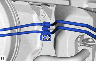
Connect a new No. 4 brake tube clamp and the brake tube to the body.
-
CONNECT VACUUM HOSE
Connect the vacuum hose to the brake vacuum check valve assembly, and slide the clip to secure it.
INSTALL BRAKE MASTER CYLINDER SUB-ASSEMBLY
INSTALL LOWER NO. 1 INSTRUMENT PANEL AIRBAG ASSEMBLY (w/ Driver Side Knee Airbag)
INSTALL LOWER INSTRUMENT PANEL FINISH PANEL (w/o Driver Side Knee Airbag)
INSTALL COWL BODY MOUNTING REINFORCEMENT RH
Install the cowl body mounting reinforcement RH with the 2 nuts.
50 N*m
510 kgf*cm
37 ft.*lbf
INSTALL COWL TOP PANEL OUTER SUB-ASSEMBLY
Install the cowl top panel outer sub-assembly with the 13 bolts.
5.5 N*m
56 kgf*cm
49 in.*lbf
INSTALL COWL VENTILATOR HOUSING SUB-ASSEMBLY
Engage the 3 clips to install the cowl ventilator housing sub-assembly.
INSTALL WINDSHIELD WIPER MOTOR AND LINK ASSEMBLY
CONNECT CABLE TO NEGATIVE BATTERY TERMINAL
Note:When disconnecting the cable, some systems need to be initialized after the cable is reconnected (Click here).
BLEED BRAKE SYSTEM
BLEED CLUTCH LINE (for Manual Transaxle)
for 2AD-FTV:
2AR-FE:
for 3ZR-FE:
for 3ZR-FAE:
for 2WW:
INSPECT AND ADJUST BRAKE PEDAL