ECD SYSTEM Starter Signal Circuit
| DTC Code | DTC Name |
|---|---|
| Starter Signal Circuit |
DESCRIPTION
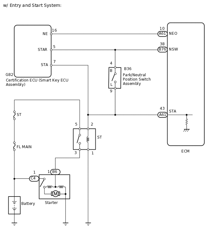
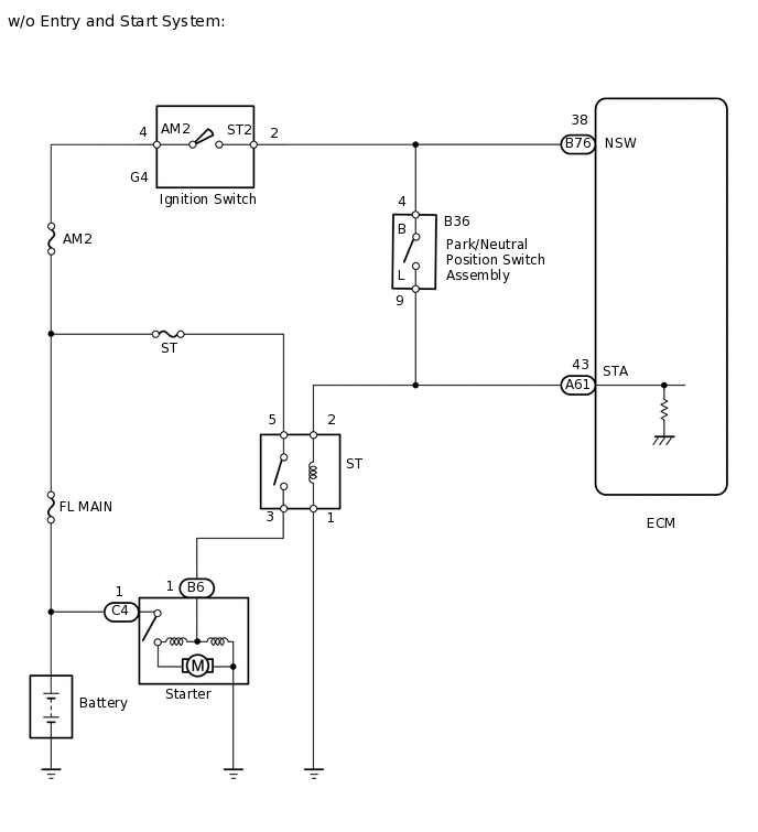
While the engine is being cranked, current flows from terminal ST2 of the ignition or starter switch assembly*1 or terminal STAR of the certification ECU (smart key ECU assembly)*2 to the clutch start switch assembly and to terminal STA of the ECM (STA signal).
*1: w/o entry and start system
*2: w/ entry and start system
WIRING DIAGRAM
CAUTION / NOTICE / HINT
Inspect the fuses of circuits related to this system before performing the following inspection procedure.
After replacing the ECM, the new ECM needs registration (Click here) and initialization (Click here).
PROCEDURE
CHECK WHETHER ENGINE CAN BE CRANKED
Check if the engine can be cranked.
Result
Proceed to
Engine cannot be cranked
Engine can be cranked
Engine can be cranked READ VALUE USING GTS (STARTER SIGNAL)Click here
READ VALUE USING GTS (STARTER SIGNAL)
Connect the GTS to the DLC3.
Turn the ignition switch to ON.
Turn the GTS on.
Enter the following menus: Powertrain / Engine / Data List / All Data / Starter Signal.
Powertrain > Engine > Data List
Tester Display
Starter Signal
Check the value displayed on the GTS when the ignition switch is turned to the ON and START positions.
OK
Switch Position
Starter Signal
ON
OFF
START
ON
Result
Proceed to
OK
NG
NG INSPECT PARK/NEUTRAL POSITION SWITCH ASSEMBLYClick here
INSPECT ST RELAY
Inspect the ST relay.
Result
Proceed to
OK
NG
NG REPLACE ST RELAY
INSPECT STARTER ASSEMBLY
Inspect the starter assembly.
Result
Proceed to
OK
NG
CHECK HARNESS AND CONNECTOR (ST RELAY - STARTER ASSEMBLY)
Remove the ST relay from the engine room relay block and junction block assembly.
Disconnect the starter assembly connector.
Measure the resistance according to the value(s) in the table below.
Standard Resistance
Tester Connection
Condition
Specified Condition
3 (ST relay) - B6-1
Always
Below 1 Ω
3 (ST relay) or B6-1 - Body ground
Always
10 kΩ or higher
Result
Proceed to
OK
NG
NG REPAIR OR REPLACE HARNESS OR CONNECTOR
CHECK TERMINAL VOLTAGE (POWER SOURCE OF STARTER ASSEMBLY)
Disconnect the starter assembly connector.
Measure the voltage according to the value(s) in the table below.
Standard Voltage
Tester Connection
Condition
Specified Condition
C4-1 - Body ground
Always
11 to 14 V
Result
Proceed to
OK
NG
NG REPAIR OR REPLACE HARNESS OR CONNECTOR
CHECK TERMINAL VOLTAGE (POWER SOURCE OF ST RELAY)
-
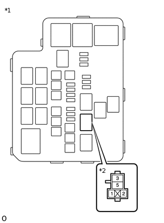
*1
Engine Room NO. 2 Relay Block and Junction Block Assembly
*2
ST Relay
Remove the ST relay from the engine room NO. 2 relay block and junction block assembly.
Measure the voltage according to the value(s) in the table below.
Standard Voltage
Tester Connection
Condition
Specified Condition
5 (ST relay) - Body ground
Always
11 to 14 V
Result
Proceed to
OK
NG
NG REPAIR OR REPLACE HARNESS OR CONNECTOR (BATTERY - ST RELAY)
-
CHECK HARNESS AND CONNECTOR (ST RELAY - BODY GROUND)
Remove the ST relay from the engine room NO. 2 relay block and junction block assembly.
Measure the resistance according to the value(s) in the table below.
Standard Resistance
Tester Connection
Condition
Specified Condition
1 (ST relay) - Body ground
Always
Below 1 Ω
Result
Proceed to
OK
NG
NG REPAIR OR REPLACE HARNESS OR CONNECTOR
CHECK HARNESS AND CONNECTOR (ST RELAY - PARK/NEUTRAL POSITION SWITCH ASSEMBLY)
Remove the ST relay from the engine room NO. 2 relay block and junction block assembly.
Disconnect the park/neutral position switch assembly connector.
Measure the resistance according to the value(s) in the table below.
Standard Resistance
Tester Connection
Condition
Specified Condition
2 (ST relay) - B36-9 (L)
Always
Below 1 Ω
2 (ST relay) or B36-9 (L) - Body ground
Always
10 kΩ or higher
Result
Proceed to
OK
NG
NG REPAIR OR REPLACE HARNESS OR CONNECTOR
INSPECT PARK/NEUTRAL POSITION SWITCH ASSEMBLY
Inspect the park/neutral position switch assembly.
Result
Proceed to
OK (w/ entry and start system)
OK (w/o entry and start system)
NG
OK (w/o entry and start system) INSPECT IGNITION OR STARTER SWITCH ASSEMBLYClick here
CHECK HARNESS AND CONNECTOR (CERTIFICATION ECU (SMART KEY ECU ASSEMBLY) - PARK/NEUTRAL POSITION SWITCH ASSEMBLY)
Disconnect the certification ECU (smart key ECU assembly) connector.
Disconnect the park/neutral position switch assembly connector.
Measure the resistance according to the value(s) in the table below.
Standard Resistance
Tester Connection
Condition
Specified Condition
G82-5 (STAR) - B36-4 (B)
Always
Below 1 Ω
G82-5 (STAR) or B36-4 (B) - Body ground
Always
10 kΩ or higher
Result
Proceed to
OK
NG
NG REPAIR OR REPLACE HARNESS OR CONNECTOR
CHECK HARNESS AND CONNECTOR (PARK/NEUTRAL POSITION SWITCH ASSEMBLY - ECM)
Disconnect the park/neutral position switch assembly connector.
Remove the ST relay from the engine room relay block and junction block assembly.
Disconnect the ECM connector.
Disconnect the certification ECU (smart key ECU assembly) connector.
Measure the resistance according to the value(s) in the table below.
Standard Resistance
Tester Connection
Condition
Specified Condition
B36-9 (L) - A61-43 (STA)
Always
Below 1 Ω
B36-9 (L) or A61-43 (STA) - Body ground
Always
10 kΩ or higher
Result
Proceed to
OK
NG
OK GO TO ENTRY AND START SYSTEM
NG REPAIR OR REPLACE HARNESS OR CONNECTOR
INSPECT IGNITION OR STARTER SWITCH ASSEMBLY
Inspect the ignition or starter switch assembly.
Result
Proceed to
OK
NG
CHECK HARNESS AND CONNECTOR (IGNITION OR STARTER SWITCH ASSEMBLY - PARK/NEUTRAL POSITION SWITCH ASSEMBLY)
Disconnect the ignition or starter switch assembly connector.
Disconnect the park/neutral position switch assembly connector.
Measure the resistance according to the value(s) in the table below.
Standard Resistance
Tester Connection
Condition
Specified Condition
G4-2 (ST2) - B36-4 (B)
Always
Below 1 Ω
G4-2 (ST2) or B36-4 (B) - Body ground
Always
10 kΩ or higher
Result
Proceed to
OK
NG
NG REPAIR OR REPLACE HARNESS OR CONNECTOR
CHECK HARNESS AND CONNECTOR (PARK/NEUTRAL POSITION SWITCH ASSEMBLY - ECM)
Disconnect the park/neutral position switch assembly connector.
Remove the ST relay from the engine room NO. 2 relay block and junction block assembly.
Disconnect the ECM connector.
Measure the resistance according to the value(s) in the table below.
Standard Resistance
Tester Connection
Condition
Specified Condition
B36-9 (L) - A61-43 (STA)
Always
Below 1 Ω
B36-9 (L) or A61-43 (STA) - Body ground
Always
10 kΩ or higher
Result
Proceed to
OK
NG
OK REPAIR OR REPLACE HARNESS OR CONNECTOR (BATTERY - IGNITION OR STARTER SWITCH ASSEMBLY)
NG REPAIR OR REPLACE HARNESS OR CONNECTOR
READ VALUE USING GTS (STARTER SIGNAL)
Connect the GTS to the DLC3.
Turn the ignition switch to ON.
Turn the GTS on.
Enter the following menus: Powertrain / Engine / Data List / All Data / Starter Signal.
Powertrain > Engine > Data List
Tester Display
Starter Signal
Check the value displayed on the GTS when the ignition switch is turned to the ON and START positions.
OK
Switch Position
Starter Signal
ON
OFF
START
ON
Result
Proceed to
OK
NG
NG REPAIR OR REPLACE HARNESS OR CONNECTOR (ST RELAY - ECM)