SFI SYSTEM(w/ Canister Pump Module), Diagnostic DTC:P0115,P0117 and P0118
| DTC Code | DTC Name |
|---|---|
| P0115 | Engine Coolant Temperature Circuit Malfunction |
| P0117 | Engine Coolant Temperature Circuit Low Input |
| P0118 | Engine Coolant Temperature Circuit High Input |
DESCRIPTION
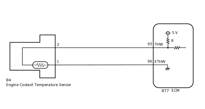
A thermistor, whose resistance value varies according to the engine coolant temperature, is built into the engine coolant temperature sensor. The structure of the sensor and its connection to the ECM are the same as those of the intake air temperature sensor.
When DTC P0115, P0117 or P0118 is stored, the ECM enters fail-safe mode. During fail-safe mode, the engine coolant temperature is estimated to be 80°C (176°F) by the ECM. Fail-safe mode continues until a pass condition is detected.
DTC No. |
Detection Item |
DTC Detection Condition |
Trouble Area |
MIL |
Memory |
|---|---|---|---|---|---|
P0115 |
Engine Coolant Temperature Circuit Malfunction |
An open or short in the engine coolant temperature sensor circuit for 0.5 seconds (1 trip detection logic). |
|
Comes on |
DTC stored |
P0117 |
Engine Coolant Temperature Circuit Low Input |
A short in the engine coolant temperature sensor circuit for 0.5 seconds (1 trip detection logic). |
|
Comes on |
DTC stored |
P0118 |
Engine Coolant Temperature Circuit High Input |
An open in the engine coolant temperature sensor circuit for 0.5 seconds (1 trip detection logic). |
|
Comes on |
DTC stored |
When any of these DTCs are output, check the engine coolant temperature using the GTS. Enter the following menus: Powertrain / Engine and ECT / Data List / Primary / Coolant Temp.
Temperature Displayed |
Malfunction |
|---|---|
-40°C (-40°F) |
Open circuit |
Higher than 135°C (275°F) |
Short circuit |
MONITOR DESCRIPTION
The engine coolant temperature sensor is used to monitor the engine coolant temperature. The engine coolant temperature sensor has a thermistor with a resistance that varies according to the temperature of the engine coolant. When the coolant temperature is low, the resistance in the thermistor increases. When the temperature is high, the resistance drops. These variations in resistance are reflected in the output voltage from the sensor. The ECM monitors the sensor voltage and uses this value to calculate the engine coolant temperature. When the sensor output voltage deviates from the normal operating range, the ECM interprets this as a fault in the engine coolant temperature sensor circuit and stores a DTC.
Example:
If the sensor output voltage is higher than 4.91 V for 0.5 seconds or more, the ECM determines that there is an open in the engine coolant temperature sensor circuit, and stores DTC P0118. Conversely, if the voltage output is less than 0.14 V for 0.5 seconds or more, the ECM determines that there is a short in the sensor circuit, and stores DTC P0117.
MONITOR STRATEGY
Frequency of Operation |
Continuous |
CONFIRMATION DRIVING PATTERN
Turn the engine switch on (IG) and wait for 5 seconds or more.
WIRING DIAGRAM
CAUTION / NOTICE / HINT
Read freeze frame data using the GTS. The ECM records vehicle and driving condition information as freeze frame data the moment a DTC is stored. When troubleshooting, freeze frame data can help determine if the vehicle was moving or stationary, if the engine was warmed up or not, if the air fuel ratio was lean or rich, and other data from the time the malfunction occurred.
If DTC P0117 is stored, check that the engine does not overheat (the DTC P0117 may be stored due to engine overheating).
PROCEDURE
READ VALUE USING GTS (COOLANT TEMP)
Connect the GTS to the DLC3.
Turn the engine switch on (IG).
Turn the GTS on.
Enter the following menus: Powertrain / Engine and ECT / Data List / Primary / Coolant Temp.
Powertrain > Engine and ECT > Data List
Tester Display
Coolant Temp
Read the value displayed on the GTS.
Standard value
Between 75 and 100°C (167 and 212°F) with warm engine.
Result
Result
Proceed to
-40°C (-40°F)
A
Higher than 135°C (275°F)
B
Between 75 and 100°C (167 and 212°F)
C
Tip:If there is an open circuit, the GTS indicates -40°C (-40°F).
If there is a short circuit, the GTS indicates higher than 135°C (275°F).
B READ VALUE USING GTS (CHECK FOR SHORT IN WIRE HARNESS)Click here
READ VALUE USING GTS (CHECK FOR OPEN IN WIRE HARNESS)
Disconnect the engine coolant temperature sensor connector.
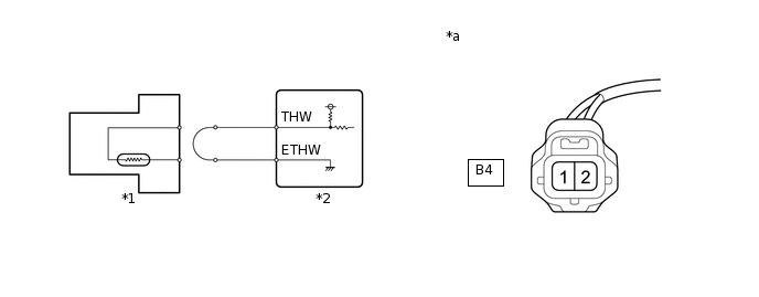
*1
Engine Coolant Temperature Sensor
*2
ECM
*a
Front view of wire harness connector
(to Engine Coolant Temperature Sensor)
-
-
Connect terminals 1 and 2 of the engine coolant temperature sensor connector on the wire harness side.
Connect the GTS to the DLC3.
Turn the engine switch on (IG).
Turn the GTS on.
Enter the following menus: Powertrain / Engine and ECT / Data List / Primary / Coolant Temp.
Powertrain > Engine and ECT > Data List
Tester Display
Coolant Temp
Read the value displayed on the GTS.
Standard value
Higher than 135°C (275°F)
Tip:Perform "Inspection After Repair" after replacing the engine coolant temperature sensor.
Result
Proceed to
OK
NG
CHECK HARNESS AND CONNECTOR (ENGINE COOLANT TEMPERATURE SENSOR - ECM)
Disconnect the engine coolant temperature sensor connector.
Disconnect the ECM connector.
Measure the resistance according to the value(s) in the table below.
Standard Resistance
Tester Connection
Condition
Specified Condition
B4-2 - B77-95 (THW)
Always
Below 1 Ω
B4-1 - B77-96 (ETHW)
Always
Below 1 Ω
Result
Proceed to
OK
NG
NG REPAIR OR REPLACE HARNESS OR CONNECTOR
READ VALUE USING GTS (CHECK FOR SHORT IN WIRE HARNESS)
-
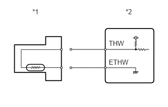
*1
Engine Coolant Temperature Sensor
*2
ECM
Disconnect the engine coolant temperature sensor connector.
Connect the GTS to the DLC3.
Turn the engine switch on (IG).
Turn the GTS on.
Enter the following menus: Powertrain / Engine and ECT / Data List / Primary / Coolant Temp.
Powertrain > Engine and ECT > Data List
Tester Display
Coolant Temp
Read the value displayed on the GTS.
Standard value
-40°C (-40°F)
Tip:Perform "Inspection After Repair" after replacing the engine coolant temperature sensor.
Result
Proceed to
OK
NG
-
CHECK HARNESS AND CONNECTOR (ENGINE COOLANT TEMPERATURE SENSOR - ECM)
Disconnect the engine coolant temperature sensor connector.
Disconnect the ECM connector.
Measure the resistance according to the value(s) in the table below.
Standard Resistance
Tester Connection
Condition
Specified Condition
B4-2 or B77-95 (THW) - Body ground
Always
10 kΩ or higher
Result
Proceed to
OK
NG
NG REPAIR OR REPLACE HARNESS OR CONNECTOR