SHIFT LEVER INSTALLATION
CAUTION / NOTICE / HINT
Use the same procedure for RHD and LHD vehicles.
The procedure listed below is for LHD vehicles.
PROCEDURE
INSTALL SHIFT LEVER ASSEMBLY
Note:Check that the park/neutral position switch and shift lever are in neutral.
Install the shift lever assembly with the 4 nuts.
12 N*m
122 kgf*cm
9 ft.*lbf
Connect the 2 connectors and attach the 2 clamps to connect the wire harness to the shift lever.
CONNECT TRANSMISSION CONTROL CABLE ASSEMBLY
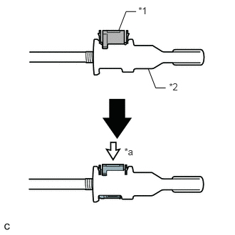
Turn the nut of the transmission control cable assembly 180° counterclockwise. While holding the nut in place, push in the stopper until it clicks twice.
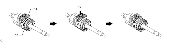
Table 1. Text in Illustration *1
Stopper
*2
Nut
*a
Push in
-
-
Install the outer part of the transmission control cable assembly to the shift lever assembly. Check that the spring is positioned at "A" and push in the stopper.
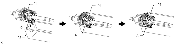
Table 2. Text in Illustration *1
Stopper
*2
Nut
*3
Shift Lever Assembly
*4
Spring
Tip:If the stopper cannot be pushed in, slightly turn the nut clockwise and then push in the stopper again.
-
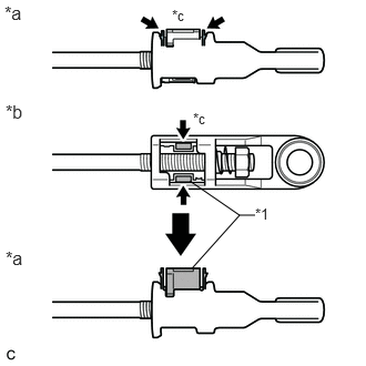
Push the 2 claws together at the top of the transmission control cable lock piece. While holding the 2 claws together, push the 2 lugs on the bottom of the lock piece toward each other and upward to pull out the lock piece.
Table 3. Text in Illustration *1
Lock Piece
*a
Side View
*b
Bottom View
*c
Push
-
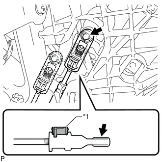
Coat the end of the transmission control cable assembly with MP grease.
Connect the end of the transmission control cable assembly to the shift lever assembly.
Note:Make sure that the lock piece is pulled up.
Push on the end of the transmission control cable assembly all the way to the base of the pin.
Table 4. Text in Illustration *1
Lock Piece

MP grease
-
Push the lock piece into the adjuster case.
Table 5. Text in Illustration *1
Lock Piece
*2
Adjuster Case
*a
Push in
Note:Securely push in the lock piece until it locks.
INSPECT SHIFT LEVER POSITION
ADJUST SHIFT LEVER POSITION
INSTALL LOWER NO. 1 INSTRUMENT PANEL FINISH PANEL