FUEL SYSTEM ON-VEHICLE INSPECTION
PROCEDURE
CHECK FUEL PUMP OPERATION AND INSPECT FOR FUEL LEAK
Check fuel pump operation.
Connect the GTS to the DLC3.
Turn the ignition switch to ON and turn the GTS on.
Note:Do not start the engine.
Enter the following menus: Powertrain / Engine and ECT / Active Test / Actuator Test of FPC (EU5).
Check for pressure in the fuel inlet tube from the fuel line. Check that sounds of fuel flowing from the fuel tank can be heard. If no sounds can be heard, check the No. 1 integration relay, fuel suction with pump and gauge tube assembly, ECM and wiring connectors.
Inspect for fuel leaks.
Check that there are no fuel leaks from the fuel system after doing any maintenance or repairs. If there is a fuel leak, repair or replace parts as necessary.
Turn the ignition switch off.
Disconnect the GTS from the DLC3.
CHECK FUEL PRESSURE
Measure the battery voltage according to the value(s) in the table below.
Standard Voltage
Tester Connection
Condition
Specified Condition
Positive (+) terminal - Negative (-) terminal
Ignition switch off
11 to 14 V
Disconnect the cable from the negative (-) battery terminal.
Remove the No. 1 fuel filter protector (Click here).
-
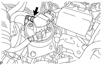
Disconnect the No. 3 fuel hose from the fuel filter assembly (Click here).
-
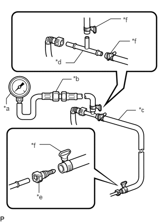
Install SST (pressure gauge) using other SST as shown in the illustration.
09268-45101
09268-41250
09268-41260
09268-41280
09268-41500
09268-41700
95336-08070
Table 1. Text in Illustration *a
SST (Pressure Gauge)
*b
SST (Hose Joint)
*c
SST (Hose)
*d
SST (T Joint)
*e
SST (Fuel Tube Connector)
*f
SST (Hose Band)
Note:Do not use SST that were used for working with gasoline.
Use different SST when working with gasoline and diesel fuel.
Clean up any spilled diesel fuel.
Connect the cable to the negative (-) battery terminal.
Connect the GTS to the DLC3.
Enter the following menus: Powertrain / Engine and ECT / Active Test / Actuator Test of FPC (EU5).
Measure the fuel pressure.
Standard fuel pressure
450 to 700 kPa (4.6 to 7.1 kgf/cm2, 65 to 102 psi)
If the fuel pressure is higher than the standard value, check the fuel filter.
If the fuel pressure is less than the standard value, check the fuel hoses, connections and fuel pump.
Disconnect the GTS from the DLC3.
Start the engine.
Measure the fuel pressure at idle.
Standard fuel pressure
450 to 700 kPa (4.6 to 7.1 kgf/cm2, 65 to 102 psi)
Stop the engine.
Reconnect the No. 3 fuel hose to the fuel filter assembly (Click here).
Install the No. 1 fuel filter protector (Click here).
Inspect for fuel leaks (Step 1).
CHECK FUEL PRESSURE (for High Pressure)
Read the Data List.
Note:In the table below, the values listed under "Normal Condition" are reference values. Do not depend solely on these reference values when deciding whether a part is faulty or not.
Tip:Using the GTS to read the Data List allows the values or states of switches, sensors, actuators and other items to be read without removing any parts. This non-intrusive inspection can be very useful because intermittent conditions or signals may be discovered before parts or wiring is disturbed. Reading the Data List information early in troubleshooting is one way to save diagnostic time.
Warm up the engine.
Turn the ignition switch off.
Connect the GTS to the DLC3.
Turn the ignition switch to ON.
Turn the GTS on.
Enter the following menus: Powertrain / Engine and ECT / Data List / Target Common Rail Pressure and Common Rail Pressure.
Check that the internal fuel pressure of the common rail is within the specification below.
OK
Common Rail Pressure is within +/-10000 kPa of Target Common Rail Pressure when the engine is idling and running at 3000 rpm without load.
CHECK PRESSURE DISCHARGE VALVE
Connect the GTS to the DLC3.
Start the engine.
Turn the GTS on.
Enter the following menus: Powertrain / Engine and ECT / Active Test / Actuator Test of Pressure Control Valve.
OK
Condition
Specified Condition
5% (Fuel Pressure Control valve OFF)
Normal engine speed
95% (Fuel Pressure Control valve ON)
The engine stops
CHECK FUEL FILTER WARNING LIGHT AND DRAIN WATER
Check the fuel filter multi-information display.
Note:When the fuel system warning is displayed on the multi-information display, replace the fuel filter (Click here) or drain the water in the fuel filter.
Drain water.
Remove the air cleaner cap sub-assembly with air cleaner hose assembly (Click here).
Remove the air cleaner element sub-assembly.
Remove the air cleaner case sub-assembly (Click here).
-
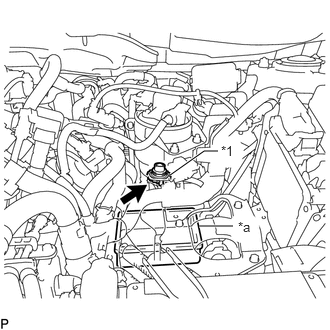
Place the container under the fuel filter assembly and loosen the drain cock to drain the water.
Table 2. Text in Illustration *1
Drain Cock
*a
Container
Tighten the drain cock by hand.
Note:Do not use any tools in this procedure.
Install the air cleaner case sub-assembly (Click here).
Install the air cleaner element sub-assembly.
Install the air cleaner cap sub-assembly with air cleaner hose assembly (Click here).