ДВИГАТЕЛЬ ПРОВЕРКА БЕЗ СНЯТИЯ С АВТОМОБИЛЯ

-
INSPECT ENGINE COOLANT
-
INSPECT ENGINE OIL
-
INSPECT BATTERY
-
INSPECT V-RIBBED BELT TENSIONER ASSEMBLY
-
CHECK VALVE LASH ADJUSTER NOISE
-
Rev the engine several times. Check that the engine does not emit unusual noises.
If unusual noises occur, warm up the engine and idle it for more than 30 minutes. Then perform the inspection above again.
If any defects or problems are found during the inspection above, perform a valve lash adjuster inspection Click here.
-
-
INSPECT AIR CLEANER FILTER ELEMENT SUB-ASSEMBLY
-
Remove the air cleaner filter element sub-assembly.
-
Visually check that there is no dirt, blockage, or damage to the air cleaner filter element.
Tech Tips
-
If there is any dirt or a blockage in the air cleaner filter element, clean it with compressed air.
-
If any dirt or a blockage remains even after cleaning the air cleaner filter element with compressed air, replace it.
-
-
-
INSPECT ENGINE IDLE SPEED
-
Warm up and stop the engine.
-
When using the GTS:
Tech Tips
-
For more information about the GTS, refer to its operator's manual.
-
If the GTS is not available, use a tachometer as a substitute.
-
Connect the GTS to the DLC3.
-
Start the engine and idle it.
-
Enter the following menus: Powertrain / Engine and ECT / Data List / Engine Speed.
Standard idle speed 650 to 750 rpm
-
-
When not using the GTS:
-
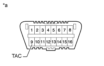
Text in Illustration *a Front view of DLC3 Connect a tester probe of a tachometer to terminal 9 (TAC) of the DLC3 with SST.
- SST
- 09843-18040
-
Start the engine and idle it.
-
-
Inspect the engine idle speed.
Standard idle speed 650 to 750 rpm Note
-
Turn all the electrical systems and A/C off.
-
When checking the idle speed, move the shift lever to neutral.
-
-
Turn the ignition switch off.
-
Disconnect the GTS or tachometer tester probe from the DLC3.
-
-
INSPECT MAXIMUM SPEED
-
Start the engine.
-
Fully depress the accelerator pedal.
-
Check the maximum engine speed.
Maximum engine speed 4450 to 4750 rpm
-
-
INSPECT COMPRESSION
-
Warm up and stop the engine.
-
Remove the 4 injector assemblies Click here.
-
Inspect the cylinder compression pressure.
-
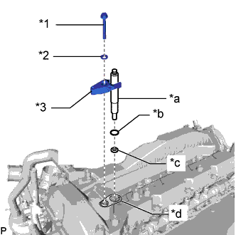
Text in Illustration *1 Bolt *2 Washer *3 Nozzle Holder Clamp *a SST (Attachment I) *b New O-Ring *c New Injection Nozzle Seat *d New Nozzle Holder Gasket Install a new nozzle holder gasket, new injection nozzle seat, new O-ring, SST (attachment I), nozzle holder clamp and washer to the cylinder head cover sub-assembly with the bolt.
- SST
- 09992-19015 ( 09992-10120 )
- Torque:
- 21 N*m { 214 kgf*cm, 15 ft.*lbf }
-
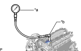
Text in Illustration *a SST (Compression Gauge) *b SST (L-Joint) Connect SST (gauge assembly), SST (packing set) and SST (L-joint) to SST (attachment I).
- SST
- 09992-19015 ( 09992-10010, 09992-10020, 09992-10030 )
-
While cranking the engine, measure the compression pressure.
Standard compression pressure 2700 kPa (27.5 kgf/cm2, 392 psi) or higher Minimum pressure 2200 kPa (22.4 kgf/cm2, 319 psi) Difference between each cylinder 500 kPa (5.1 kgf/cm2, 73 psi) or less Note
-
Use a fully-charged battery so the engine speed can be increased to 280 rpm or more.
-
Inspect the other cylinders in the same way.
-
Measure the compression as quickly as possible.
-
-
If the cylinder compression is low, pour a small amount of engine oil into the cylinder through the injector holes, and then inspect it again.
If adding oil increases the compression pressure, the piston rings and/or cylinder bore may be worn or damaged.
If the pressure stays low, the valve may be stuck or seated improperly, or there may be leakage from the gasket.
-
-
Remove SST.
-
Install the 4 injector assemblies Click here.
-