КЛАПАН ПЕРЕКЛЮЧЕНИЯ ПОДАЧИ ВОЗДУХА (для моделей с вспомогательной системой подачи воздуха в нейтрализатор) УСТАНОВКА
-
INSTALL AIR SWITCHING VALVE ASSEMBLY
-
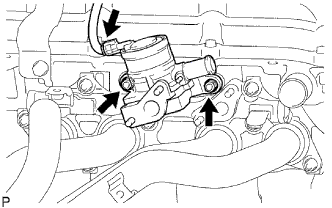
Install the valve with 2 new nuts.
- Torque:
- 20 N*m { 204 kgf*cm, 15 ft.*lbf }
-
Connect the connector.
-
-
INSTALL INTAKE PIPE INSULATOR
-
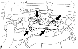
Install 2 new gaskets and the pipe with 4 new nuts.
- Torque:
- 20 N*m { 204 kgf*cm, 15 ft.*lbf }
-
Check that the nuts are tightened to the torque specification.
Note
Tightening the nuts only once is not enough to tighten them to the torque specification.
-
-
INSTALL NO. 1 EXHAUST MANIFOLD HEAT INSULATOR
-
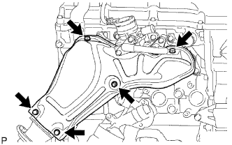
Install the heat insulator with the 5 bolts.
- Torque:
- 12 N*m { 122 kgf*cm, 9 ft.*lbf }
-
-
CONNECT NO. 4 AIR HOSE
-
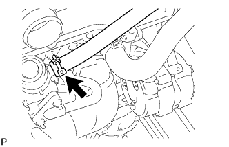
Connect the No. 4 hose to the switching valve.
-
Secure the hose with the clamp.
-
-
INSTALL AIR CLEANER ASSEMBLY
-
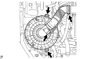
Connect the air cleaner hose.
-
Install the air cleaner with the 2 bolts.
- Torque:
- 14 N*m { 143 kgf*cm, 10 ft.*lbf }
-
Tighten the hose clamp.
- Torque:
- 4.0 N*m { 41 kgf*cm, 35 in.*lbf }
-
Connect the MAF meter connector.
-
-
CONNECT CABLE TO NEGATIVE BATTERY TERMINAL
-
PERFORM INITIALIZATION
-
Perform initialization Click here.
CAUTION:
Certain systems need to be initialized after disconnecting and reconnecting the cable from the negative (-) battery terminal.
-