AUTOMATIC TRANSAXLE ASSEMBLY INSTALLATION

PROCEDURE
-
INSTALL TRANSFER AND TRANSAXLE SETTING STUD BOLT
-
Transfer Side:
-
Clean the bolt holes.
-
Apply adhesive 1324 to 2 or 3 threads on one half of a new transfer and transaxle setting stud bolt A as shown in the illustration.
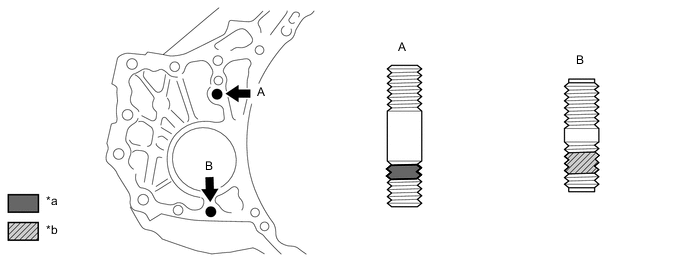
*a Toyota Genuine Adhesive 1324 *b Sealant - Torque:
- 39.2 N*m { 400 kgf*cm, 29 ft.*lbf }
Adhesive Toyota Genuine Adhesive 1324, Three Bond 1324 or equivalent Note
-
Do not apply adhesive 1324 to the ends of the stud bolt.
-
Install the stud bolt immediately after applying adhesive to prevent the adherence of foreign matter.
-
-
INSTALL TRANSFER ASSEMBLY
-
INSTALL TORQUE CONVERTER ASSEMBLY
-
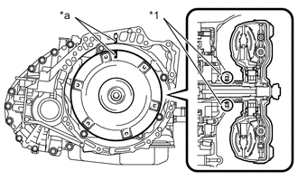
*1 Front Oil Pump Oil Seal *a Matchmark Align the matchmark on the transaxle housing with the one on the torque converter assembly and engage the splines of the input shaft with the turbine runner splines.
Note
-
Install the torque converter assembly to the input shaft while keeping it horizontal.
-
Do not damage the front oil pump oil seal.
-
-
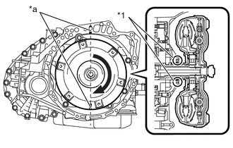
*1 Front Oil Pump Oil Seal *a Matchmark Rotate the torque converter assembly approximately 180° and engage the splines of the stator shaft with the stator assembly.
Note
-
Install the torque converter assembly to the input shaft while keeping it horizontal.
-
Do not damage the front oil pump oil seal.
-
-
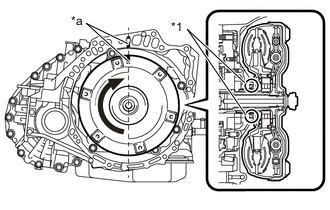
*1 Front Oil Pump Oil Seal *a Matchmark Rotate the torque converter assembly approximately 180° again, align the matchmark on the torque converter assembly with the one on the transaxle housing and insert the groove of the torque converter assembly into the key of the oil pump drive gear.
Note
-
Do not push the torque converter assembly excessively when rotating it.
-
Install the torque converter assembly to the input shaft while keeping it horizontal.
-
Do not damage the front oil pump oil seal.
-
-
Clean the drive plate and torque converter assembly set bolt holes.
-
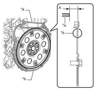
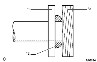
*a Engine Surface *b Drive Plate Surface Using a vernier caliper and straightedge, measure the dimension A between the automatic transaxle assembly contact surface of the engine assembly*a and the torque converter assembly contact surfaces of the drive plate*b.
-
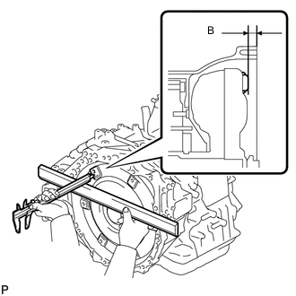
Using a vernier caliper and straightedge, measure the dimension B shown in the illustration and check that the dimension B is more than dimension A, which was measured in the previous step.
Standard A + 1 mm (0.0394 in.) or more Note
-
Make sure to deduct the thickness of the straightedge.
-
If the automatic transaxle assembly is installed to the engine assembly with the torque converter assembly not sufficiently inserted, the torque converter assembly may be damaged.
-
Do not include the thickness of the set block.
-
-
-
INSTALL AUTOMATIC TRANSAXLE ASSEMBLY
-
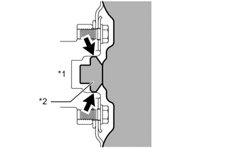
*1 Crankshaft *2 Torque Converter Assembly Centerpiece Apply clutch spline grease to the surface of the crankshaft that contacts the torque converter assembly centerpiece.
Clutch spline grease Toyota Genuine Clutch Spline Grease or equivalent Maximum grease amount Approximately 1 g (0.0353 oz.) -
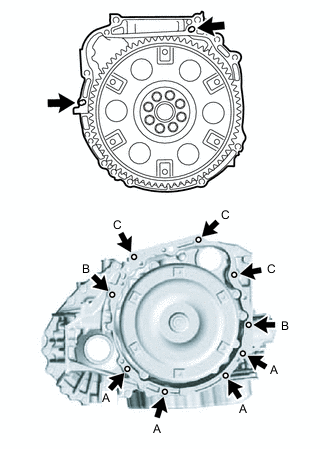
While keeping the engine and automatic transaxle assembly horizontal, align the knock pins with the holes in the automatic transaxle assembly and install the 9 bolts shown in the illustration.
- Torque:
- for bolt A
- 43 N*m { 438 kgf*cm, 32 ft.*lbf }
- for bolt B
- 46 N*m { 469 kgf*cm, 34 ft.*lbf }
- for bolt C
- 64 N*m { 653 kgf*cm, 47 ft.*lbf }
Bolt Length Bolt Length (mm (in.)) A 33 mm (1.30) B 50 mm (1.97) C 55 mm (2.17) Note
-
Confirm that the 2 knock pins are installed to the transaxle contact surface of the engine cylinder block before installing the automatic transaxle assembly.
-
Do not forcibly pry on the automatic transaxle assembly.
-
Check that the drive plate rotates smoothly after installation of the automatic transaxle assembly.
-
-
INSTALL BREATHER HOSE CLAMP
-
Install the breather hose clamp to the transmission breather hose sub-assembly.
-
-
INSTALL TRANSMISSION CASE PLUG ASSEMBLY
-
Coat the O-ring with ATF.
-
Install the transmission case plug assembly to the automatic transaxle assembly.
-
-
INSTALL WIRING HARNESS CONNECTOR
-
Install the wiring harness connector to the automatic transaxle assembly.
-
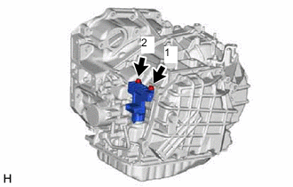
Install and tighten the 2 bolts in the sequence shown in the illustration.
- Torque:
- 11.3 N*m { 115 kgf*cm, 8 ft.*lbf }
-
-
INSTALL NO. 1 TRANSMISSION CONTROL CABLE BRACKET
-
Install the No. 1 transmission control cable bracket to the automatic transaxle assembly with the 2 bolts.
- Torque:
- 12 N*m { 122 kgf*cm, 9 ft.*lbf }
-
-
INSTALL REAR ENGINE MOUNTING BRACKET
-
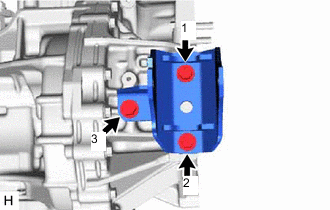
Temporarily install the rear engine mounting bracket to the automatic transaxle assembly with the 3 bolts.
-
Tighten the 3 bolts in the sequence shown in the illustration.
- Torque:
- 45 N*m { 459 kgf*cm, 33 ft.*lbf }
-
-
INSTALL ENGINE MOUNTING BRACKET LH
-
Clean the bolts and the installation holes in the engine mounting bracket LH.
-
Apply adhesive to 2 or 3 threads on the ends of the 4 bolts.
Adhesive Toyota Genuine Adhesive 1324, Three Bond 1324 or equivalent -
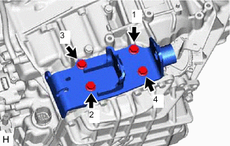
Temporarily install the engine mounting bracket LH to the automatic transaxle assembly with the 4 bolts.
-
Tighten the 4 bolts in the sequence shown in the illustration.
- Torque:
- 64 N*m { 653 kgf*cm, 47 ft.*lbf }
-
-
INSTALL FRONT ENGINE MOUNTING BRACKET
-
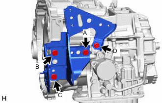
Temporarily install the front engine mounting bracket to the automatic transaxle assembly with the 4 bolts.
-
Tighten the 4 bolts in the sequence shown in the illustration.
- Torque:
- for bolt A, B, C
- 64 N*m { 653 kgf*cm, 47 ft.*lbf }
- for bolt B
- 13.5 N*m { 138 kgf*cm, 10 ft.*lbf }
-
-
INSTALL TRANSMISSION OIL COOLER
-
Temporarily install the transmission oil cooler to the front engine mounting bracket with the 2 bolts.
-
Tighten the 3 bolts.
- Torque:
- 13.5 N*m { 138 kgf*cm, 10 ft.*lbf }
-
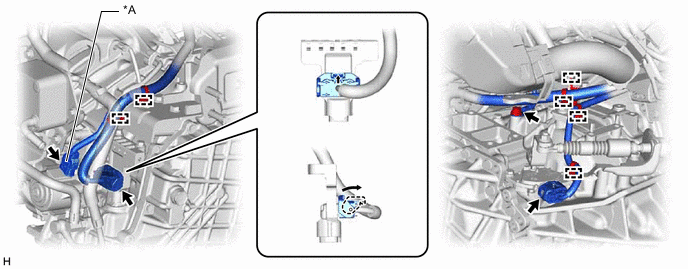
w/ Air Cooled Transmission Oil Cooler:
Connect the oil cooler inlet hose, and slide the clip to secure it.
Note
-
Make sure to insert the oil cooler inlet hose until the spool fitting so that the marking is facing the front of the vehicle.
-
Make sure to install the hose clip in a direction that does not interfere with other parts.
-
Make sure to install the hose clip so that the spool fitting is not overlapped.
-
-
w/o Air Cooled Transmission Oil Cooler:
Connect the oil cooler inlet hose and oil cooler outlet hose, and slide the 2 clips to secure them.
Note
-
Make sure to insert the oil cooler inlet hose and oil cooler outlet hose until the spool fitting so that the marking is facing the front of the vehicle.
-
Make sure to install the hose clips in a direction that does not interfere with other parts.
-
Make sure to install the hose clips so that the spool fitting is not overlapped.
-
-
-
INSTALL WIRE HARNESS CLAMP BRACKET
-
Install the 2 wire harness clamp brackets to the automatic transaxle assembly with the 2 bolts.
- Torque:
- 19 N*m { 194 kgf*cm, 14 ft.*lbf }
-
-
CONNECT WIRE HARNESS
-
Attach the 5 wire harness clamps and connect the park/neutral position switch connector.
*a w/ Stop and Start System - -
w/ Stop and Start System:
Connect the oil with motor pump connector.
-
Connect the connector to the wiring harness connector and turn the lock lever and secure the connector with the lock lever.
-
Connect the park/neutral position switch connector.
-
Connect the ground cable with the bolt.
- Torque:
- 20 N*m { 204 kgf*cm, 15 ft.*lbf }
-
-
INSTALL STARTER ASSEMBLY
-
INSTALL ENGINE ASSEMBLY WITH TRANSAXLE
-
INSTALL DRIVE PLATE AND TORQUE CONVERTER ASSEMBLY SETTING BOLT
-
Remove any adhesive remaining the 6 drive plate and torque converter setting assembly bolts.
-
Apply a few drops of adhesive to 2 or 3 threads at the tip of each of the 6 drive plate and torque converter assembly setting bolts.
Adhesive Toyota Genuine Adhesive 1324, Three Bond 1324 or equivalent -
Turn the crankshaft to gain access to the installation locations of the 6 drive plate and torque converter assembly setting bolts and install each bolt while holding the crankshaft pulley with SST.
- SST
- 09213-54015
- 09330-00021
- Torque:
- 41 N*m { 418 kgf*cm, 30 ft.*lbf }
Tech Tips
-
First install the black-colored bolt, and then the remaining 5 silver-colored bolts.
-
Part number of installation bolt for SST (crankshaft pulley holdingtool): 91551-80650 (quantity: 2)
-
-
INSTALL FLYWHEEL HOUSING UNDER COVER
-
Install the flywheel housing under cover.
-
-
INSTALL FRONT EXHAUST PIPE SUB-ASSEMBLY
-
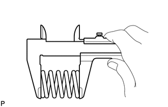
Using a vernier caliper, measure the free length of the compression spring.
Minimum length 41.5 mm (1.63 in.) If the length is less than the minimum, replace the compression spring.
-
Using a wire brush, remove any foreign matter from the gasket installation surface.
-
*1 Exhaust Manifold Converter Sub-assembly *2 Gasket *a Wooden Block Using a plastic-faced hammer and wooden block, tap in a new gasket until its surface is flush with the exhaust manifold converter sub-assembly.
Note
-
Be sure to install the gasket so that it faces the correct direction.
-
Do not reuse the gasket.
-
Do not damage the gasket.
-
When connecting the front exhaust pipe assembly, do not push in the gasket with the front exhaust pipe assembly.
-
-
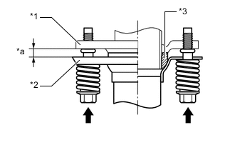
*1 Exhaust Manifold Converter Sub-assembly *2 Front Exhaust Pipe Sub-assembly *3 Gasket *a Space between flanges: 8.5 mm (0.335 in.) Install the front exhaust pipe sub-assembly to the exhaust manifold converter sub-assembly with the 2 compression springs and 2 bolts.
- Torque:
- 43 N*m { 438 kgf*cm, 32 ft.*lbf }
Tech Tips
After installation, check that the space between the flanges of the exhaust manifold converter sub-assembly and front exhaust pipe sub-assembly is consistent front-to-rear and left-to-right.
-
Install a new gasket to the front exhaust pipe sub-assembly.
-
Connect the front exhaust pipe sub-assembly to the front No. 2 exhaust pipe sub-assembly with the 2 bolts.
- Torque:
- 43 N*m { 438 kgf*cm, 32 ft.*lbf }
-
-
INSPECT FOR EXHAUST GAS LEAK
-
CHECK AUTOMATIC TRANSAXLE SYSTEM
Note
If automatic transmission parts have been replaced, refer to the Parts Replacement Compensation Table to determine if any additional operations are necessary.