SHIFT LEVER REASSEMBLY
CAUTION / NOTICE / HINT
Use the same procedure for RHD and LHD vehicles.
The procedure listed below is for LHD vehicles.
PROCEDURE
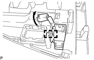
INSTALL SHIFT LOCK CONTROL ECU
-
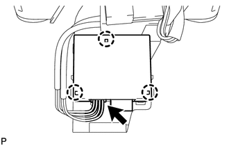
Attach the 3 claws to install the shift lock control ECU to the shift lock control unit.
Connect the shift lock solenoid connector to the shift lock control ECU.
-
INSTALL POSITION INDICATOR SLIDE COVER
-
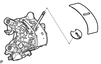
Install the No. 2 position indicator slide cover to the position indicator slide cover.
Install the position indicator slide cover together with the No. 2 position indicator slide cover to the position indicator housing.
-
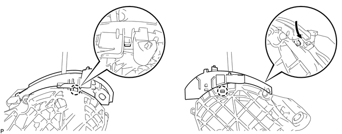
INSTALL LOWER POSITION INDICATOR HOUSING
Attach the 2 claws to install the lower position indicator housing to the shift lock control unit.
INSTALL UPPER POSITION INDICATOR HOUSING
-
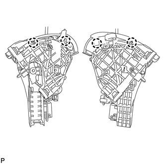
Attach the 4 claws to install the upper position indicator housing to the shift lock control unit.
-
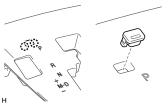
INSTALL POSITION INDICATOR LIGHT BULB
Install the cap to the bulb.
Install the bulb to the position indicator light wire socket.
INSTALL INDICATOR LIGHT WIRE SUB-ASSEMBLY
-
Align the wire socket with the key part of the position indicator housing, and install the wire. Then rotate the wire socket clockwise until it locks.
Connect the indicator light wire connector to the position indicator housing.
-
INSTALL NO. 1 PATTERN SELECT SWITCH ASSEMBLY
INSTALL SHIFT LOCK RELEASE BUTTON COVER
-
Attach the 2 claws to install the shift lock release button cover to the position indicator housing assembly.
-